GigaPico Next ManualFocus Users’ Manual 2.1 GeoDesy Kft. Telefon: 06-1-481-2050 Fax.: 06-1-481-2049 E-mail: info@geodesy-fso.com http://www.geodesy-fso.
Table of contents 1 2 3 Introduction...................................................................................................................... 4 1.1 What is FSO?........................................................................................................... 4 1.2 Why is it important? ............................................................................................... 4 1.3 Optical Free-space Transmission ..............................................................
Security ...................................................................................................................... 28 Mandatory Management Activation ........................................................................... 29 Firmware update ......................................................................................................... 30 7.2 Network Interface software update ..................................................................... 32 7.2.1 Update cabel................
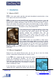
1 Introduction 1.1 What is FSO? FSO is free space optics provides point-point broadband communications using Laser Light as the transmission medium. FSO is a state of art data communication method which is based on a very old communication solution. Ancient Chinese developed a protection system against the Mongol tribes, building watchtowers within the line of site to other towers. And as soon as the towers saw some hostile sign on the horizon they use they shield to reflect the sun to the remote towers.
sensitive to sense delight emitted from the remote side. GeoDesy FSO offers high transmit power and also very hard receiver sensitivity. These two factors combined to provide one of the best performing FSO systems on the market today. To meet the demands for every higher bandwidth, GeoDesy FSO (Europe) Limited continues to invest heavily in research and development with the newest product line which offers Gigabit speeds being launched.
1.3 Optical Free-space Transmission The principle used in free space laser transmission is very similar to the one is used for fibre optic transmission. The difference is while fibre optic devices use electronics and optics optimized for transmission to the air. Also one can observe to the similarity in the transmission properties. No galvanic contact, no ground-loops, no need for surge protection, noise immunity, long distances, high bandwidth.
1.4 Typical applications Most typically the GeoDesy FSO Next product are is used to interconnect LANs. The system is protocol transparent, thus other applications also can be taken into consideration. Appropriate interface converters are needed and system bandwidth must be matched for that. Here we collected some circumstances, where the deployment of the GeoDesy FSO is the most adequate as a cost effective solution.
2 Interfaces for the Giga Next MF Series 2.1 1000Mbps TP interface The GeoDesy FSO Giga Next MF series products are designed to provide easy-to-use and cost-effective solution for interconnecting Local Area Networks. By utilizing standard Category 5e cable and using standard IEEE802.3af interface the deployment of the system is easier than ever before. The transparent and wire speed data transfer together with virtually zero latency assures the easy integration of the system in all environments.
3 Sites of installation 3.1 Key factors of operation There are four key issues that the site survey has to shed light on. Proper system operation cannot be guaranteed without satisfying all of the four requirements. Clear line of sight - The entire optical path between the two ends must be free of any obstacles. It not only means that one has to see the other side, but other possible sources of disturbance should also be taken into consideration.
its specified direction. Another important consideration is to provide enough space for alignment and to have the potential for future maintenance. Consider that the support frame is usually heavy, so the selected spot should be easily accessible.
3.3 Distance measurement Because the units were designed, and calibrated for certain distance operations the higher distance will decrease the availability. GeoDesy FSO pre-calibrates and pretests every unit shipped to the customer. To ensure that the unit you are about to buy fits to the needs, the first step is to measure the distance. The best way to measure it is by GPS (Global Positioning System), these units are accurate enough to determine the distance between two points.
4 Eye safety There are no two installation spots of the same kind, the buildings or structures, the available space and the accessibility of the place will be different in each case. Nevertheless, as a general rule it is very important to select the installation site so that nobody can look directly into the transmitter.
5 The mounting bracket In the following chapter you will find detailed description of the bracket fastenings. 5.1 Mounting brackets for the X Series GeoDesy FSO provides the mounting bracket and all the necessary components for X series units.
Packet list for the bracket: 3pcs 8x110 screw for bracket fixing 3pcs 8x100 plastic wall-plug for bracket fixing 2pcs M6x90 bolt Head fixing 3pcs M6x25 screw Head fixing 3pcs M6 bolt head fixing 6pcs 6mm spacer bracket and head fixing 6pcs 6mm spring spacer bracket and head fixing Mounting Hole Patterns GeoDesy Kft. Telefon: 06-1-481-2050 Fax.: 06-1-481-2049 E-mail: info@geodesy-fso.com http://www.geodesy-fso.
6 System installation 6.1 On the table test Warning! Do not look either into the transmitter or the receiver optics because at this distance even the reflected laser beam can be dangerous to your eyes. Operating the system on much shorter distance than presumed originally can cause saturation or even permanent damage to the receiver. Always use optical attenuators for this kind of test. The on-the-table test needs careful planning and careful use during the test period.
6.1.1 Alignment of the PX0400E1000TP The first step after the unit was placed to the bracket, and the units facing each other. On the back of the receiver you can find the LEDs and LCD screen for the local received level and the remote received level. This help will be very useful because as soon as you have received – which is very easy to achieve – you can see the effect of your local sides movement to the other side. For further information please check the Meanings of the LCDs chapter. 6.1.
6.1.3 Fine tuning 1. Site A start moving the laserhead with the horizontal fine adjustment screw by looking at the Remote end received level 2. Using the fine adjustment screws, lighten as many LEDs as possible 3. Repeat step 1-2 on Site B. 4. If necessary try step 1-2 on both sites again. 6.2 Meanings of the LCD Power: The head is powered up. RX-OK: Received beam is good for communication. TP Lk: Copper link between the head and the Network equipment.
6.3 Manual Beam Adjustment Note! The Beam Adjustment is designed to be used by experts only, please contact trained personnel before adjusting the system. Unauthorized adjustment of the beam divergence control may result permanent link loss and unreliable operation. Do not over power the screw! In normal case the screw can be turned with a very little force. If you feel that the screw is hard to rotate, please stop rotating it.
Note: Geodesy FSO shall not be responsible for any failures from improper handling of the device. If any other screw than the coarse lockers or the fine adjustment is moved, might decrease the stability of the installation. Trick for the reliable alignment Please note that the beam has a powerfull ring on the side of the head and easily can be set to this ring but this is far not as big as the core part of the beam.
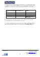
6.4 Connecting to your Network 6.4.1 PoE 802.3 af connection. 1. Orange/White 2. Orange 3. Green/White 4. Blue 5. Blue/White 6. Green 7. Brown/White 8. Brown TX+ TX RX+ +VIN +VIN RX-VIN -VIN 6.4.2 System layout GeoDesy Kft. Telefon: 06-1-481-2050 Fax.: 06-1-481-2049 E-mail: info@geodesy-fso.com http://www.geodesy-fso.
6.4.3 System layout with GEO20 Beside the GeoDesy laser equipment (buckup) you can only use GeoDesy’s GEO20 Radio equipment. In the case of using a different backup solution, could cause undesired operation. Please referr to support@geodesy-fso.com for more inforamation about the compatibility. GeoDesy Kft. Telefon: 06-1-481-2050 Fax.: 06-1-481-2049 E-mail: info@geodesy-fso.com http://www.geodesy-fso.
7 Management 7.1 Features The Inband network-monitoring unit is a newly developed highly featured monitoring for GeoDesy FSO manufactured laser links. This high quality equipment allows the user to monitor the link statuses such as detector voltage transmitter status, and many other features of the Laser link. Nevertheless, this chapter is intended to describe the usage of this network monitoring, and its connection and relationship with the GeoDesy FSO laserheads.
Head Serial Number: This is the head serial number and during the Activation process we will ask for this number. Status info screen Clicking on the Device Setup you will enter the main status information screen, which will give you good summarized information of the device, such as status information of the transmitters, detector level, or temperature values. Laser ON: Transmitter transmitts Temperature: ambient temperature inside the device.
Device setup The device setup screen leads you to the main monitoring options. Here the alarms can be set and main information about the Laser head. Device name: uniqe identifier of the device Managed head: Type of the laserhead Temperature alert level: when the temperature reach this value, the alarm will be triggered. Auto recovery time: It determines the time before the heads start the recovery process in the case of link disconnection.
Software version: software of the laser head. NPASW SW version: Network Port Auto SWitchover version. GBIC-compatibility mode:On or OFF. If there are two connectors under the laser head them the GBIC-compatibility mode should be ON (the is GBIC-module in it) but if there are 3 or 4 them the GBICcompatibility modeshould be OFF (the is NPASW module it).
Subnet mask: you can set the subnet mask of the local device. Default gateway: The default getway setting for the local device. Auto MDI/MDI-X: this enables the Auto setting for the MDI/MDI-X, some old switch types might report incompatibility here it can be switched off. (Auto MDI/MDI-X can be turned off even in the Xs systems) Remote IP:This will tell this device what the IP address of the remote device is.
SNMP Setup One of the main features of the device is the SNMP(Simple Network Monitoring Protocol). The SNMP settings can be set on this page. Trap address: The IP address of the SNMP trap over the network. Trap events in the system you have possibility to setup three different trap event. For further details on the trap event see Trap event list chapter of this book. In this section there are the settings of the SNMP Agent.
Security On the security section you can set the username and the password for the unit. If you have forget the usernam and/or the password please contact The technical support. MGM Trusted-host filtering: Here you can adjust two addresses wehre you can till in from which computer with you reach the MGM! To adjust you will hove to adjust a filter. Filter adjust: Off: Turned off. IP: Only see the IP address. MAC: Only see the MAC address IP+MAC: Either IP or MAC address should be equal to the adjusted.
Mandatory Management Activation Thank you for buying our product. Please read this note carefully. From software version (3.2.1218/R090x)! The product you have bought has fully functional management software, which has limitation only in time. The unit activation request should be sent to activation@geodesy-fso.com. And the activation code will be issued, later and sent to the email address give, or can be accessed from your local distributor.
Firmware update The firmware update has the following steps: Run FTP client Log-in to the Laser-head Copy Geodesy_FWUpdate_Vxx.sys over Log in the laserhead Click on update Wait 50-60 seconds Restart the laserhead Run FTP client FTP client setup IP address: the IP address of the device (192.168.100.220 or 192.168.100.221 as a factory default ) or the IP address you gave to the system earlier – same as the IP address for the Web management.
copy the file over to the Laserhead Log off the FTP server Now the Update button will be active Click on update and the update process will start it takes upto 60 seconds. The LEDs on the back of the device will go off than lit one after the other. Make sure that the system power is fixed and the power will not go off during the update process. If the LEDs froze, wait 2-3 minutes before unplugging the power cable, and repluging again. GeoDesy Kft. Telefon: 06-1-481-2050 Fax.
7.2 Network Interface software update 1. Connect the RJ11 and RS232 cable (update cabel) between the laser head and the PC. 2. Enter into the management of the laser head and into the device info. 4.Click on the „Update” button. 5.Click on OK button. 6. Start the Total Commander program and start PIC32.exe program. 7. Choose COM1 port. 8.Click ont the Connect button. 9.Click on Erase button. GeoDesy Kft. Telefon: 06-1-481-2050 Fax.: 06-1-481-2049 E-mail: info@geodesy-fso.com http://www.geodesy-fso.
10. Click on Load Hex File button and then choose the attached .HEX file (new software) 11.Click on the Program button. 12.Click on Run application button: the laser head will restart with the new software. 13. Click on the Disconnect button and close the program. GeoDesy Kft. Telefon: 06-1-481-2050 Fax.: 06-1-481-2049 E-mail: info@geodesy-fso.com http://www.geodesy-fso.
7.2.1 Update cabel GeoDesy Kft. Telefon: 06-1-481-2050 Fax.: 06-1-481-2049 E-mail: info@geodesy-fso.com http://www.geodesy-fso.