GeoMax Zoom70/90 User Manual Version 2.
Introduction Purchase Congratulations on the purchase of the GeoMax Zoom70/90. This manual contains important safety directions as well as instructions for setting up the product and operating it. Refer to "1 Safety Directions" for further information. Read carefully through the User Manual before you switch on the product. ☞ The content of this document is subject to change without prior notice. Ensure that the product is used in accordance with the latest version of this document.
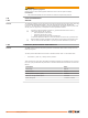
NOTICE Zoom_019 Do NOT remove the battery during operation of the instrument, or during the shutdown procedure. This can result in a file system error and data loss! Always switch off the instrument by pressing the On/Off key, and wait until the instrument has shutdown completely before removing the battery.
Table of Contents 1 Safety Directions 1.1 1.2 1.3 1.4 1.5 1.6 1.7 1.8 2 Description of the System 2.1 2.2 2.3 2.4 3 4.8 4.9 4.10 4.11 6 4 20 21 21 22 22 23 24 26 27 27 29 29 30 32 32 34 35 35 35 35 37 37 38 40 Unit Settings Date/Time Settings Communication Settings Atmospheric Settings Apps 6.1 6.2 20 29 Main Menu System Information Setting Up the TPS Instrument Setting up for Remote Control (with the RadioHandle) Connecting to a Personal Computer Power Functions Batteries 4.7.
6.3 7 Adjusting the Circular Level of the Instrument and Tribrach Adjusting the Circular Level of the Prism Pole Inspecting the Laser Plummet of the Instrument Servicing the Tripod 47 48 48 49 49 Care and Transport 7.1 7.2 7.3 7.4 8 6.2.4 6.2.5 6.2.6 6.2.7 Format 50 Transport Storage Cleaning and Drying Maintenance 50 50 50 51 Technical Data 8.1 8.2 8.3 8.4 8.5 8.6 8.7 8.8 8.9 8.
1 Safety Directions 1.1 General Introduction Description The following directions enable the person responsible for the product, and the person who actually uses the equipment, to anticipate and avoid operational hazards. The person responsible for the product must ensure that all users understand these directions and adhere to them. About warning messages Warning messages are an essential part of the safety concept of the instrument. They appear wherever hazards or hazardous situations can occur.
Reasonably foreseeable misuse • • • • • • • • • • • Use of the product without instruction. Use outside of the intended use and limits. Disabling safety systems. Removal of hazard notices. Opening the product using tools, for example screwdriver, unless this is permitted for certain functions. Modification or conversion of the product. Use after misappropriation. Use of products with recognisable damages or defects.
DANGER Risk of electrocution Because of the risk of electrocution, it is dangerous to use poles, levelling staffs and extensions in the vicinity of electrical installations such as power cables or electrical railways. Precautions: ▶ Keep at a safe distance from electrical installations. If it is essential to work in this environment, first contact the safety authorities responsible for the electrical installations and follow their instructions.
CAUTION Not properly secured accessories. If the accessories used with the product are not properly secured and the product is subjected to mechanical shock, for example blows or falling, the product may be damaged or people can sustain injury. Precautions: ▶ When setting up the product, make sure that the accessories are correctly adapted, fitted, secured, and locked in position. ▶ Avoid subjecting the product to mechanical stress.
WARNING Improperly repaired equipment Risk of injuries to users and equipment destruction due to lack of repair knowledge. Precautions: ▶ Only authorised GeoMax Service Centres are entitled to repair these products. 1.6 Laser Classification 1.6.1 General General The following chapters provide instructions and training information about laser safety according to international standard IEC 60825-1 (2014-05) and technical report IEC TR 60825-14 (2004-02).
Labelling a 009823_001 a Laser beam 1.6.3 Distance, Measurements without Reflectors General The EDM module built into the product produces a visible laser beam which emerges from the telescope objective. The laser product described in this section is classified as laser class 3R in accordance with: IEC 60825-1 (2014-05): “Safety of laser products” • Direct intrabeam viewing may be hazardous (low eye hazard level), in particular for deliberate ocular exposure.
CAUTION Reflected beams aimed at reflecting surfaces Potential hazards are not only related to direct beams but also to reflected beams aimed at reflecting surfaces such as prisms, windows, mirrors, metallic surfaces, etc. Precautions: ▶ Do not aim at areas that are essentially reflective, such as a mirror, or which could emit unwanted reflections. ▶ Do not look through or beside the optical sight at prisms or reflecting objects when the laser is switched on, in laser pointer or distance measurement mode.
Direct intrabeam viewing may be hazardous (low eye hazard level), in particular for deliberate ocular exposure. The beam may cause dazzle, flash-blindness and after-images, particularly under low ambient light conditions. The risk of injury for laser class 3R products is limited because of: a) b) c) unintentional exposure would rarely reflect worst case conditions of (e.g.
Type: Zoom90... Art.No.: Equip.No.: 1234567 Power: 11.5-13.5 V ,1.4 A max 123456 GeoMax AG CH-9443 Widnau Manufactured: 20X X Made in Singapore 123456 S.No.: Complies with FDA performance standards for laser products except for deviations pursuant to Laser Notice No. 50, dated June 24, 2007. This device complies with part 15 of the FCC Rules.
Labelling a a 009823_001 Laser beam 1.6.6 Prism Search (Scout) - only available at Zoom90 General The Prism Search built into the product produces an invisible laser beam which emerges from the front side of the telescope.
Labelling a a 009829_001 Laser beam 1.6.7 Navigation Light (NavLight) General The Navigation Light built into the product produces a visible LED beam which emerges from the front side of the telescope. ☞ The product described in this section, is excluded from the scope of IEC 60825-1 (2014-05): “Safety of laser products”.
These products are safe for momentary exposures but can be hazardous for deliberate staring into the beam. The beam may cause dazzle, flash-blindness and after-images, particularly under low ambient light conditions. Description Value Wavelength 640 nm Maximum average radiant power 0.95 mW Pulse duration 0.1 ms - cw Pulse repetition frequency (PRF) 1 kHz Beam divergance <1.
WARNING Electromagnetic radiation Electromagnetic radiation can cause disturbances in other equipment. Precautions: ▶ Although the product meets the strict regulations and standards which are in force in this respect, GeoMax cannot completely exclude the possibility that other equipment may be disturbed. CAUTION Use of the product with accessories from other manufacturers.
1.8 FCC Statement, Applicable in U.S. ☞ The greyed paragraph below is only applicable for products without radio. WARNING This equipment has been tested and found to comply with the limits for a Class B digital device, pursuant to part 15 of the FCC rules. These limits are designed to provide reasonable protection against harmful interference in a residential installation.
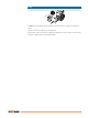
2 Description of the System 2.1 System Components System components 9832_002 Main components Component Description Zoom70/90 instrument • • • Field controller Terms and abbreviations b a a b Zoom70/90 Field controller A total station for measuring, calculating and capturing data. Consisting of various models with a range of accuracy classes. Combined with the multipurpose field controller to conduct remote control surveys.
Term Description NavLight Navigation Light A NavLight fitted to an instrument assists with prism targeting. It consists of two differently coloured flashing lights located in the instrument telescope housing. The person holding the prism can align themselves into the line of sight of the instrument. AiM Automated Prism Aiming. AiM refers to the instrument sensor which enables the automatic prism aiming. TRack Instruments fitted with Target aiming are referred to as Automated.
Software type Description The English language is integrated into the firmware and cannot be deleted. Language files (Zoom70_90_xx_yy.sxx) Numerous languages are available for the Zoom70/90 instruments. This software is also referred to as system language. xx = Language Code; yy = Country Code The English language is the default language. One language is chosen as the active language. Software upload ☞ Uploading software can take some time.
2.
2.
Instrument components for robotic a b 009839_001 a b RadioHandle Communication side cover Description of the System 25
3 User Interface 3.1 Keyboard Keyboard a b c d e f g h i j k l m n o 9840_00 2 a b c d e f g h i Function keys F7 - F9 ± key Alphanumeric keys Backspace Function keys F10 - F12 Keyboard illumination/Access: + <0> Level key/Access: + <.> ESC User key* j k l m n o Arrow keys Page key ENTER FNC ON/OFF Function keys F1 - F6 * User key is not used by GeoMax Toolkit.
Key Function Starts the edit mode for editable fields. Opens a selectable list. User key User key is not used by GeoMax Toolkit. Page key Displays the next screen when several screens are available. FNC Used for key combinations. • +<0> to toggle keyboard illumination. • +<.> to go to the digital level. Navigation key Controls the focus bar within the screen and the entry bar within a field. 3.2 Softkeys Description Softkeys are selected using the relevant F1 to F6 function keys.
Edit fields Operation Description To highlight an item or parts of it for editing Drag the supplied stylus from the left to the right. To accept data entered into an editable field and exit the edit mode Tap on the screen outside of the editable field. ☞ ESC Deletes any change and restores the previous value. Moves the cursor to the left Moves the cursor to the right. Sets focus to the previous setting. Sets focus to the next setting.
4 Operation 4.1 Main Menu Description The MAIN MENU is the starting place for accessing most functionality of the instrument. It is displayed when selecting the GeoMax Toolkit from the WinCE main screen. MAIN MENU Description of the MAIN MENU functions Function Description 1 Level To select and open Level Up screen. Refer to " Level up with the electronic level step-by-step". 2 Sysinfo To select and start Sysinfo. Refer to "4.2 System Information". 3 Settings To select and start Settings.
System information Page 1 Field Description Instrument Model Displays the type name of the instrument. Serial Number Displays the serial number of instrument. Equipment Number Displays the equipment number of instrument. Angle Accuracy Displays the accuracy of angle measurement. EDM Displays the type of EDM. Page 2 Page 2 displays several version numbers of software and hardware components. Page 3 4.
3. Turn on the instrument by pressing . Activate the laser plummet and electronic level by pressing the key combination +<.> or by starting up the GeoMax Toolkit and selecting from MAIN MENU: Level. 4. Level up with the electronic level step-by-step Move the tripod legs (1) and use the tribrach footscrews (6) to centre the plummet (4) over the ground point. 5. Adjust the tripod legs to level the circular level (7). 6.
4.4 Setting up for Remote Control (with the RadioHandle) Setup for remote control with the RadioHandle e a f b g c d a b c d e f g 9856_002 Prism Prism pole Field controller with Bluetooth Holder RadioHandle Instrument Tripod 4.
Connect USB cable to computer for the first time step-by-step 2 4 3 011050_001 1. Start the computer. 2. Plug the USB cable into TPS instrument. 3. Turn on the TPS instrument. 4. Plug the USB cable into the USB port of the computer. The Found New Hardware Wizard starts up automatically. 5. Check Yes, this time only. Next>. 6. Check Install the software automatically (Recommended). Next>. The software for Remote NDIS based GeoMax Device will be installed on your computer 7. Finish. 8.
☞ ActiveSync starts up automatically. If does not start automatically, start ActiveSync. If not already installed, run the ActiveSync installation program. 5. Allow USB connections inside the Connection Settings window of ActiveSync. 6. Click Explore in ActiveSync. ☞ The directories on the Zoom70/90 instrument are displayed under Mobile Devices. For computers with Windows Vista or Windows 7/Windows 8 operating system: ☞ Windows Mobile Device Center starts up automatically.
4.7 Batteries 4.7.1 Operating Principles First-time use/ charging batteries • The battery must be charged before using it for the first time because it is delivered with an energy content as low as possible. The permissible environment is only indoor conditional and temperature range for charging is between 0 °C to +40 °C/+32 °F to +104 °F. For optimal charging, we recommend charging the batteries at a low ambient temperature of +10 °C to +20 °C/+50 °F to +68 °F if possible.
Insert and remove an SD card step-by-step 1 2 4a 4b 3 (5) 009858_001 ☞ The SD card is inserted into a slot inside the Communication side cover of the instrument. 1. Turn the knob on the Communication side cover to the vertical position to unlock the communication compartment. 2. Open the lid of the communication compartment to access the communication ports. 3. To insert the SD card, slide it firmly into the SD slot until it clicks into position.
4.9 Working with Bluetooth Description Zoom70/90 instruments can communicate with external devices by a Bluetooth connection. The instrument Bluetooth is a slave only. The Bluetooth of the external device will be the master, and therefore will control the connection and any data transfer. Establishing a connection step-by-step 1. On the instrument, ensure that the communication parameters are set to Internal Bluetooth or Bluetooth Handle. Refer to "5.3 Communication Settings". 2.
IF the Link LED Data Transfer LED Mode LED 4.11 is THEN green power is on. off no radio link to field controller. red radio link to field controller. off no data transfer to/from field controller. green or green flashing data transfer to/from field controller. off data mode. red configuration mode.
☞ As with all other instrument errors, the collimation error of the automatic aiming must be redetermined periodically. Refer to "6.2 Calibration" about checking and adjusting instruments. ☞ When a measurement is triggered while the prism is still moving, distance and angle measurements may not be made for the same position and coordinates may vary. ☞ If the prism location is changed too quickly, the target may be lost. Make sure that the speed does not exceed the figure given in the technical data.
5 Settings 5.1 Unit Settings Access 1. Select Settings from the MAIN MENU. 2. Select Unit from the SETTINGS menu. UNIT SETTINGS DEFAULT To set all values to factory default. Field Description Angle Sets the units shown for all angular fields. ☞ Degree decimal. Possible angle values: 0° to 359.999° mil Mil. Possible angle values: 0 to 6399.99mil. °'" Degree sexagesimal. Possible angle values: 0° to 359°59'59'' Sets the units shown for all distance and coordinate related fields.
DATE / TIME Field Description Time (24h) Displays the current time. Date Displays the current date as an example of the selected date format. Format dd.mm.yyyy mm.dd.yyyy yyyy.mm.dd Displays how the date is shown in all date-related files. 5.3 Communication Settings Description For data transfer the communication parameters of the instrument must be set. Access 1. Select Settings from the MAIN MENU. 2. Select Comm. from the Settings menu.
Configuration Bluetooth DEFAULT To set all values to factory default. Field Description Pin The Pin code needed to communicate to the instrument. The default value is 0000. Before the new Pin will be active, a reboot of the system would be required. Configuration RS232 DEFAULT To set all values to factory default. Field Description Baudrate Speed of data transfer from receiver to device in bits per second. 1200, 2400, 4800, 9600, 14400, 19200, 38400, 57600, 115200 Parity Even Even parity.
5.4 Access Atmospheric Settings 1. Select Settings from the MAIN MENU. 2. Select Atmos. from the SETTINGS menu. ATMOSPHERIC SETTINGS DEFAULT To set all values to factory default. Field Description Z(MSL) Sets the elevation above mean sea level. Temperature Sets the temperature. Pressure Sets the pressure. Humidity Sets the humidity. Atmos PPM The atmospheric ppm is calculated from the values in the previous fields. Refr. Coeff Refraction coefficient to be used for calculation. Use Refr.
6 Apps 6.1 Update Description The GeoMax Toolkit software can be loaded via a SD card. This process is described below. Access ☞ 1. Select Apps from the MAIN MENU. 2. Select Update from the APPS menu. Never disconnect power supply during data transfer. Battery capacity must be at least 75% capacity before commencing the upload. Loading firmware, languages and key step-by-step 1. To load firmware, select Firmware. To load license keys: Select Key. The Select File! screen appears.
Mechanical adjustment The following instrument parts can be adjusted mechanically: • • • Precise measurements To get precise measurements in the daily work, it is important: • • • ☞ 6.2.2 ☞ To check and adjust the instrument from time to time. To take high precision measurements during the check and adjust procedures. To measure targets in two faces. Some of the instrument errors are eliminated by averaging the angles from both faces.
☞ Before starting to work, the instrument has to become acclimatised to the ambient temperature. Approximately two minutes per °C of temperature difference from storage to working environment, but at least 15 min, should be taken into account. ☞ Even after adjustment of the AiM, the crosshairs may not be positioned exactly on the centre of the prism after an AiM measurement has been completed. This outcome is a normal effect.
8. + 27° V= 90 ° - 27° Aim the telescope accurately at a visual target at about 100 m distance or less if not possible. No distance reading is taken during these steps so a prism target is not required. The visual target must be positioned at least 27 °/30 gon above or beneath the horizontal plane. 011051_001 9. Press OK to measure and continue to the next step. 10. 180° 180° Motorised instruments change automatically to the other face.
4. ☞ 6.2.5 Check the position of the circular level on the instrument and tribrach: a) If both circular levels are centred, no adjustments are necessary. b) If one or both circular levels are not centred, adjust as follows: • Instrument: If it extends beyond the circle, use the supplied allen key to centre it with the adjustment screws. Turn the instrument by 200 gon (180°). Repeat the adjustment procedure if the circular level does not stay centred.
2. Using the tribrach footscrews, level the instrument with the electronic level. 3. Access the electronic level and laser plummet by using the key-combination +<.> or by starting GeoMax Toolkit and go to MAIN MENU screen and select Level. 4. The laser plummet is switched on automatically when the Level up screen is entered. Adjust the laser plummet intensity. Inspection of the laser plummet should be carried out on a bright, smooth and horizontal surface, like a sheet of paper. 5.
7 Care and Transport 7.1 Transport Transport in the field When transporting the equipment in the field, always make sure that you • • Transport in a road vehicle either carry the product in its original container, or carry the tripod with its legs splayed across your shoulder, keeping the attached product upright. Never carry the product loose in a road vehicle, as it can be affected by shock and vibration. Always carry the product in its container and secure it.
Cables and plugs Keep plugs clean and dry. Blow away any dirt lodged in the plugs of the connecting cables. 7.4 Maintenance ☞ An inspection of the motorisation in motorised instruments must be done in a GeoMax authorised service centre. GeoMax recommends an inspection of the product every 12 months. For instruments which are in intensive or permanent use, for example tunnelling or monitoring, the recommended inspection cycle may be reduced.
8 Technical Data 8.1 Angle Measurement Accuracy Available angular accuracies Standard deviation Hz, V, ISO 17123-3 Display resolution ["] [mgon] ["] 1 0.3 0.1 2 0.6 0.1 5 1.5 0.1 Characteristics Absolute, continuous, diametric. 8.
The display resolution is 0.1 mm. Characteristics Principle: Phase measurement Type: Coaxial, visible red laser Carrier wave: 658 nm Measuring system: System analyser basis 100 MHz - 150 MHz 8.
Laser dot size Type Description Carrier wave 658 nm Measuring system System Analyzer Basis 100 MHz - 150 MHz Distance [m] Laser dot size, approximately [mm] at 30 7 x 10 at 50 8 x 20 at 100 16 x 25 8.4 Distance Measurement - Long Range (LO mode) Range The range of the long range measurements is the same for A5 and A10.
8.
AiM accuracy Automatic target aiming accuracies, like those of the AiM, are in general the same as the stated angular accuracy. Therefore these accuracies are also distance-dependent parameters. External impacts, like heat shimmer, rain (prism surface covered by rain drops), fog, dust, strong background lights, dirty targets, alignment of the targets etc. can have a significant influence on the automated target. In addition the selected EDM mode affects the AiM performance.
Measurements at the vertical limits of the fan or under unfavourable atmospheric conditions may reduce the maximum range. (*optimally aligned to the instrument) Shortest measuring distance: Searching Characteristics 1.5 m Type Value Typical search time <10 s Default search area Hz: 400 gon, V: 40 gon Definable search windows Yes Type Description Principle Digital signal processing Type Infrared laser 8.7 Conformity to National Regulations 8.7.
Class 1 equipment according to European Directive 2014/53/EU (RED) can be placed on the market and be put into service without restrictions in any EEA member state. • Frequency band The conformity for countries with other national regulations not covered by the FCC part 15 or European Directive 2014/53/EU has to be approved prior to use and operation. Value Limited to 2402 - 2480 MHz Output power Value < 100 mW (e. i. r. p.
Level Control unit Instrument Ports Angular accuracy instrument ["] Setting accuracy Setting range ["] [mgon] [’] [gon] 2 0.5 0.2 4 0.07 5 1.5 0.5 4 0.
Recording Component Value Tribrach 0.8 kg Internal battery 0.2 kg Data can be recorded onto an SD card or into internal memory. Type Laser plummet Capacity SD card 1 GB Internal memory 1 GB Type Drives Value Type Visible red laser class 2 Location In standing axis of instrument Accuracy Deviation from plumb line:1.5mm (2 sigma) at 1.5m instrument height Diameter of laser point 2.5mm at 1.
Humidity Reflectors Type Protection All instruments Max 95 % non condensing The effects of condensation are to be effectively counteracted by periodically drying out the instrument. Type Additive Constant [mm] AiM Scout Standard prism, ZPR100 0 yes yes Mini prism, ZMP100 0 yes yes Mini prism, ZMP101 +17.5 yes yes 360° prism, ZPR1 / GRZ122 +23.1 yes yes 360° Mini prism, GRZ101 +30.0 yes not recommended Reflector tape S, M, L +34.4 yes no Reflectorless +34.
Air temperature to 1 °C Air pressure to 3 mbar Relative humidity to 20 % • • • Air humidity The air humidity influences the distance measurement if the climate is extremely hot and damp. For high precision measurements, the relative humidity must be measured and entered along with the air pressure and the temperature.
Reduction to mean sea level DD2 The values for DD2 are always negative and are derived from the following formula: H ΔD2= - R TS_106 Atmospheric corrections °C DD2 H R · 106 Reduction to mean sea level [ppm] Height of EDM above sea level [m] 6.378 * 106 m Atmospheric corrections in ppm with temperature [°C], air pressure [mb] and height [m] at 60% relative humidity.
8.
• • • To prisms To reflector tape Reflectorless measurements Technical Data 65
9 Software Licence Agreement Software Licence Agreement This product contains software that is preinstalled on the product, or that is supplied to you on a data carrier medium, or that can be downloaded by you online according to prior authorisation from GeoMax.
10 Glossary Instrument axis SA KA ZA ZA SA KA SA SA V ZA KA V VK Hz0 Hz HK TSOX_002 Plumb line / compensator Standing axis inclination KA SA VK Hz HK = Line of sight / collimation axis Telescope axis = line from the cross hairs to the center of the objective. = Standing axis Vertical rotation axis of the telescope. = Tilting axis Horizontal rotation axis of the telescope. Also known as the Trunion axis.
Zenith Point on the plumb line above the observer. Crosshairs Glass plate within the telescope with reticle. Line-of-sight error (horizontal collimation) The line-of-sight error (c) is the deviation from the perpendicular between the tilting axis and line of sight. This could be eliminated by measuring in both faces. c TS0X_005 Vertical index error i TS0X_006 68 Glossary With a horizontal line of sight the vertical circle reading should be exactly 90°(100 gon).
Appendix A Menu Tree ☞ Depending on local firmware versions the menu items may differ. Menu Tree GeoMax Toolkit |—— Level |—— Sysinfo |—— Settings | | | | |—— Unit | | | |—— Date/Time | | | |—— Comm. | | | |—— Atmos. ||| | | | |—— |—— |—— |—— Angle, Distance, Temperature, Pressure Time(24h), Date, Format RS232, Bluetooth Handle, Internal Bluetooth Z(MSL), Temperature, Pressure, Humidity, Atmos PPM, Refr. Coeff, Use Refr. C. |—— Apps | | | | |—— Update | | | |—— Calib.
Appendix B Directory Structure Description On the USB memory stick, files are stored in certain directories. The following diagram is the default directory structure.
Appendix C Pin Assignments Description Some applications require knowledge of the pin assignments for the instrument port. In this chapter, the pin assignments and socket for the RS232 port of the Zoom70/90 instrument are explained. Ports at the Zoom70/90 instrument a 4 5 1 3 2 a 011059_001 Pin assignments for RS232 port 1 2 3 PIN_006 5 4 RS232 Pin Signal Name Function Direction 1 PWR Nominal 12 V ⎓, Range 11.5 V-13.5 V, 1.
837009-2.1.0en Original text © 2018 GeoMax AG, Widnau, Switzerland GeoMax AG www.geomax-positioning.