SUNSHINE FLASH SUN 11 8 User and Installation Guide offered by Busse-Yachtshop.
READ THIS WARNING BEFORE USING THE GEONAV THE ELECTRONIC CHART IS AN AID TO NAVIGATION DESIGNED TO FACILITATE THE USE OF AUTHORIZED GOVERNMENT CHARTS, NOT TO REPLACE THEM. ONLY OFFICIAL GOVERNMENT CHARTS AND NOTICES TO MARINERS CONTAIN ALL INFORMATION NEEDED FOR THE SAFETY OF NAVIGATION AND, AS ALWAYS, THE CAPTAIN IS RESPONSIBLE FOR THEIR PROPER USE. The use of the GEONAV implies knowledge and acceptance of this warning by the user.
4 INTRODUCTION The GEONAV is a chart plotter that can be interfaced with a GPS receiver, autopilot and other onboard instruments, and allows displaying the boat’s geographical position with respect to an electronic chart. Thanks to the GEONAV and a NAVIONICS electronic chart, you will never get lost even in case of fog, rain or dark. The GEONAV, available with either sunlight-readable color display or sunlight-readable monochrome display, has been designed to allow flush mounting.
6 Flash • Color LCD, TFT 10.4” Sun • Monochrome LCD, STN 9.4” Sunshine 11 • Color LCD, transflective TFT 10.4”, high brightness, sunlight visible Sunshine 8 • Color LCD, TFT 6.4”, sunlight visible Electrical characteristics • Power supply: 10 to 36 Vd.c. Flash Sun • Power consumption: Max. 13 W Sunshine 8 • Power consumption: Max. 16 W Sunshine 11 • Power consumption: Max. 20 W • • Flash Sun • NMEA 2000 network load: 2 Auxiliary voltage output: 10 to 36 Vd.c.
8 Installation and Precautions 9 INSTALLATION AND PRECAUTIONS Precautions To avoid electromagnetic interference, the GEONAV must be positioned at least 0.72 m (Flash, Sun), 0.50 m (Sunshine 11) or 0.45 m (Sunshine 8) away from the magnetic compass. Wherever possible, the power supply cable shield should be connected to the boat’s ground plate. The GEONAV is water resistant but not waterproof, and should not be immersed totally in water.
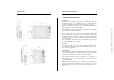
10 11 Flush mounting Locate the area where the GEONAV is to be installed, then use the cutting template supplied with the plotter to cut the panel. Bracket mounting Fix the bracket to the boat’s dashboard by screws 6mm in diameter.
Connections 12 Power supply and data connector (9 pins) 1. Power supply red wire + VDC black wire GND pin 1 pin 2 2. NMEA 0183 data input brown wire GPS IN + yellow wire GPS IN - pin 3 pin 4 3. NMEA 0183 data output violet wire DATA OUT + white wire DATA OUT - pin 5 pin 6 4. Auxiliary output voltage (Vaux) blue wire Vaux+, 250mA * green wire GND SHIELD pin 7 pin 8 pin 9 2.
14 CARTRIDGE INSTALLATION Installing the CompactFlash™ Open the cartridge slot cover located on the plotter’s front side. Insert the cartridge into the appropriate slot, with the label side (side with a small arrow) towards the right, and push it down. Close the cover exercising light pressure and check that it is perfectly closed, in order to avoid any water infiltration. 15 Removing the CompactFlash™ Make sure that the plotter is perfectly dry.
KEYBOARD ZOOM-/ZOOM+ • Increases/decreases the chart range • Enables/disables the Autozoom function JOYSTICK (right/left - up/down) • Moves the cursor across the screen • Switches from Navigation mode to Cursor mode • Selects the options from menus and submenus If pressed (ENTER): Cursor mode: • Inserts a waypoint at the cursor’s position Navigation mode: • Changes the target waypoint (Motor boating) • Sets the wind speed (Sailing) Menu: • Confirms a selection GOTO Plots a route to: • A new target waypoint
18 Cursor mode: • Switches from Cursor mode to Navigation mode Navigation mode: • Turns the pages of navigation data MARK • Inserts a marker at the boat’s position (in Navigation mode), or at the cursor’s position (in Cursor mode) PWR • Switches the GEONAV on • Opens the contrast/brightness window • Switches the GEONAV off (if held pressed for more than 3 seconds) Diagnostic 19 DIAGNOSTIC The GEONAV features a diagnostic program to verify its correct performance, once installed, and to detect problems t
NAVIONICS Electronic Charts 20 NAVIONICS ELECTRONIC CHARTS The GEONAV includes a built-in world map. Additional cartography details relative to a specific area of navigation are available from the CompactFlash™ cartridges storing NAVIONICS Seamless™ electronic charts. 21 crease the chart range by the ZOOM+ key to display the details of the area covered by the cartridge.
22 Description of navaid characteristics: ABBREVIATIONS FOR LIGHT AL alternating F fixed FLL fixed and flashing FL (...) group flashing FL single flashing IQ interrupted quick OC single-occulting OC (...) composite group occulting Q continuous group ABBREVIATIONS FOR COLOUR AM amber B black BL blue G green OR orange R red VL violet W white Y yellow ABBREVIATION FOR PERIOD ..S xx seconds ABBREVIATION FOR RANGE ..
24 Graphic Items 25 GRAPHIC ITEMS Besides chart data, the GEONAV displays some graphic items useful during navigation. The figure below shows some of these items. 1 - Marker Indicates a point of interest associated with a symbol, a name and a color. 2 - Track segment Recording of the track actually followed by the boat; the track is displayed as a colored dashed line. 3 - Boat’s position Boat’s position according to the data received from the GPS receiver.
Functional Characteristics 26 FUNCTIONAL CHARACTERISTICS tion mode. 5 - Route leg Part of route between two waypoints. This chapter describes some of the most important functions of the GEONAV, as well as the terms most commonly used in this document. 6 - Waypoint Waypoints are identified by a circle and a number. The route starting point is marked by the “X” symbol. The target waypoint is identified by a filled circle, whereas the route leg currently followed is identified by a thicker line.
28 29 NOTE: In this document, the functions enabled in Advanced and Sailing modes are outlined in the text. Unless otherwise specified, functions are intended as common to all the available modes. range before activating the chart rotation. Confirm by pressing ENTER.
Advanced 30 31 To enable the Autozoom function, press ZOOM+ until the “AUTOZOOM ? ENTER = YES” message is displayed, then confirm by pressing ENTER. To disable the Autozoom function, press ZOOM. When the GEONAV is turned on, and if at least one waypoint has been previously entered, the Autozoom function will be automatically enabled.
32 33 Overzoom The Overzoom function allows expanding the chart range. The Overzoom does not provide any additional chart detail, only improves the readability of the available information, acting as a magnifying glass. Press ENTER to move the GPS boat’s position to the point indicated by the cursor. This operation will save the calibration for use in future calculations. NOTE: When the calibration is enabled, the coordinates (latitude/longitude) in the Info window will be marked by (*).
Flash Sunshine 34 positioning the manual cursor on the segment itself. The color of chart items can be chosen from DAY, NIGHT or BRIGHT. Press the PAGE key to display the menu bar, select SETUP, DISPLAY MODE and then DAY, NIGHT or BRIGHT. Quick Tour 35 QUICK TOUR We recommend that you use the GEONAV intuitively, since no damage will be caused by pressing an incorrect button. Make sure that the GPS receiver is connected, insert a Compact Flash™ cartridge and press the PWR key.
36 The GEONAV is in Navigation mode; by the joystick, it is possible to switch to Cursor mode (editing mode). The cursor position is shown by two windows. The joystick allows moving in all directions. To plot a route starting from the boat’s position, move the cursor to the position desired, and press ENTER to insert a waypoint, that will be indicated by a circle containing the number 1. The windows will also show the time to reach the target waypoint, distance, bearing and estimated time to arrive.
38 39 OPERATING MODES NAVIGATION MODE The GEONAV will display different kinds of data, according to the operating mode currently enabled. To access these windows, press the PAGE key repeatedly. As the fix is valid, the sequence is the following: CURSOR MODE SATELLITE > MOTOR BOATING > MENU > DEPTH SOUNDER > TRIP > INFO To plan a new route, or to append waypoints to the existing route, move the cursor by using the joystick and press ENTER.
40 SATELLITE WINDOW NOTE: If a NAVIONICS cartridge with the Tides and Currents feature has been inserted, the Satellite window will disappear as soon as a valid fix is obtained and be replaced by the Info window. At start-up the satellite window displays how many and which satellites are tracked by the GPS receiver. 41 played on the left identify the signal quality; the longer the bar, the higher the signal quality. On the left of each bar, two digits indicate numerically the signal/noise ratio.
Motor Boating Windows 42 43 These windows are automatically enabled as soon as the GPS receiver has obtained a valid fix (FIX OK). When navigating in waters deeper than sounder operating range or if the boat’s speed is too high for depth sounding, data acquisition will be interrupted and the number replaced by “—”. If no route has been entered, the following data will be shown: NOTE: To display sea depth and temperature values, the GEONAV must be interfaced with a depth sounder.
44 Sailing SAILING WINDOWS Sailing 45 These windows, automatically enabled as soon as the GPS receiver has obtained a valid fix (FIX OK) and data is received from wind instruments, display the following information: • • • • • The wind graph on the right-hand side of the screen shows the true wind variation diagram with respect to the reference direction, as recorded in the last hour.
Sailing Menu 46 47 MENU The graph at the bottom of the screen shows the instantaneous shift of the true wind direction with respect to the reference direction. The menu bar, displayed at the top of the screen, allows selecting from the following options: ROUTE: To display route information, reverse and delete the route. TRACK: To enable/disable the track function, delete a track, choose the track color and show the used percentage of track memory.
48 Info Window DEPTH SOUNDER WINDOW This window, displayed if the GEONAV is interfaced with a depth sounder, replaces the number indicating the sea depth in the Motor Boating windows with a graph showing the sea bed. If received, the graph shows the water temperature as well. When navigating in waters deeper than sounder operating range or if the boat’s speed is too high for depth sounding, data acquisition will be interrupted and the number replaced by “—”.
Info Window 50 Trip Window 51 TRIP WINDOW The Trip window shows general data relating to the route followed. Average speed from departure Maximum speed from departure Time elapsed from departure Partial distance covered from departure Overall distance covered To reset all counters (except for the overall distance) before starting a new journey, press the CLR key.
52 ROUTE EDITING A ROUTE (CURSOR MODE) Creating a waypoint Using the joystick, move the cursor on the position desired and press ENTER to insert a waypoint. To enter further waypoints, move the cursor and press ENTER. The new waypoint will be appended to the existing route. Up to 99 waypoints per route can be entered, also by using the GOTO function (see the GOTO Section) and EBL/VRM functions (see the EBL/VRM Functions Section). Deleting the last waypoint Press CLR.
54 55 Press the PAGE key to display the menu, select ROUTE, INFO and press ENTER. Enter the data required and confirm by pressing ENTER. TIME: Estimated time from START to current waypoint FUEL LITERS: Estimated fuel consumption (liters or gallons) Advanced The time to arrive to the waypoint and fuel consumption are displayed provided that estimated speed and fuel consumption values have been entered (see the Entering speed and fuel consumption data Section).
Advanced Track 56 57 TRACK By selecting CURRENT, the route currently displayed will be deleted; the route can also be deleted by keeping the CLR key pressed for 3 seconds in Navigation mode. The Track function allows recording the track actually followed by the boat. The Track function can be enabled and disabled several times during navigation; in this case, separate track segments will be drawn.
Advanced 58 59 then RECALL to open the track catalog. • • • Select the track desired, then press ENTER to confirm the operation or PAGE to exit. The catalog that lists the tracks stored in the CompactFlash™ will show the CURRENT item indicating the track currently displayed. Select the track to delete by the joystick, then press ENTER to confirm. By selecting CURRENT, the track currently displayed will be deleted.
60 61 MARKERS Deleting a marker Position the cursor on the marker to delete and press CLR. Markers are used to identify points of interest to which names and symbols can be assigned. NAVIGATION MODE Inserting a marker Press the MARK key to insert a marker at the boat’s position. A window will display the symbol and the name automatically assigned to the marker; to change the marker symbol, name and color according to the type of marker to store (e.g., fishing spots, submerged wrecks, rocks, etc.
Advanced 62 The catalog that lists the sets of markers stored in the CompactFlash™ will show the CURRENT item indicating the set currently displayed. Use the joystick to select the set of markers to delete and to confirm. When selecting CURRENT, the set of markers currently displayed will be deleted. 63 SETUP Use the joystick to select the set desired and confirm, or press PAGE to exit. Deleting a set of markers Press the PAGE key to display the menu, select MARKER, DELETE and press ENTER to confirm.
• • • • • • • • • 64 Overzoom (ON/OFF) Enables/disables the Overzoom function. Calibration (ON/OFF) Allows entering the position calibration offset. Time Reference (LOCAL/GMT) Allows entering local time. Bearings (TRUE/MAGNETIC) (the number on the right indicates the magnetic variation) Allows setting the magnetic mode for all bearings. Distance Units (NAUT/METR/STAT) Allows selecting distance units. Depth Units (M/FT/FA) Allows selecting depth units.
• • • • • • 66 Time Reference (LOCAL/GMT) Allows entering local time. Select Mode (STANDARD/ADVANCED) Allows switching between standard and advanced mode. Distance Units (NAUT/METR/STAT) Allows selecting distance units. Depth Units (M/FT/FA) Allows selecting depth units. Language (EN/FR/ES/DE/IT/DK/SV/NL/SU/NO) Allows selecting the language. Welcome Message (ON/OFF) Enables/disables the display of a message in the welcome page, appearing as the instrument is turned on.
68 69 Once the desired port has been selected, the GEONAV will insert a waypoint in the port position and append the new leg to the existing route (if no route is available, the new waypoint will be connected to the boat’s position). Route to the nearest service NOTE: This option is available only with the NAVIONICS cartridges containing the Port Services features. It allows finding and heading for the nearest port featuring the service desired.
Goto 70 71 The GEONAV will position the manual cursor at the beginning of the track segment selected; insert a waypoint by pressing ENTER or a marker by pressing MARK. and Currents stations. Use the joystick to choose the station desired and to confirm. The GEONAV will move the manual cursor to the position selected; insert a waypoint by pressing ENTER or a marker by pressing MARK.
Goto 72 Autopilot 73 AUTOPILOT NOTE: The same information can be accessed by positioning the manual cursor on the icon of a Tides or Currents station, and pressing ENTER to confirm. The GEONAV allows a boat equipped with an autopilot to follow automatically the entered route, compensating for any diversion caused by external conditions (wind, currents, etc.). The GEONAV will display the “PROXIMITY TO WAYPOINT” message to warn the user that the boat is about to reach the target waypoint.
Table of Contents 75 INTRODUCTION ................................................................................ 4 CHARACTERISTICS ......................................................................... 5 INSTALLATION AND PRECAUTIONS ................................................ 9 CONNECTIONS ............................................................................... 12 CARTRIDGE INSTALLATION ........................................................... 14 KEYBOARD ...............................