
User's Manual


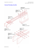
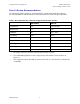


Table Of Contents

Geophysical Survey Systems, Inc. Model 4105 Antenna
System Settings and User’s Notes
MN34-559 Rev C
6
Gain: Data collection gain for the 4105 antenna should be adjusted so that the peak amplitude of
the pavement surface reflection is approximately 2/3 of the total screen width. For example, in
Figure 2 the pavement surface reflection has an amplitude of approximately 20000 and the full
screen width is 32000.
It is very important that the pavement surface reflection amplitude
(and metal plate reflection when performing calibration) never reach its maximum
(i.e., clip).
If they jump off of the top or the bottom of the window, they are collected with too
much gain. This will cause errors in the post-processing. Figure 3 shows an improperly gained
signal.
Figure 3: Example of Model 4105 data scan collected with too much gain.
Quick Setup Procedure SIR-10B/H
1. Connect the transducer cable from the SIR unit (Channel 1) to the Model 4105 antenna.
2.
Connect all other necessary cables to the SIR unit (power, video, keyboard).
3.
Turn on the SIR unit.
4.
From the Main menu select Recall Saved Radar Setting (Option 4).
5.
Select Highway Data (Option 4).
6.
From the list of antenna configurations select “2G”.
7.
Back in the Main menu, select Collect Radar Data (Option 2).
8.
A message will appear on the screen indicating that settings have been changed, then the
screen should change and you should see a signal similar to the signal shown in Figure 2 on
the right side of the screen. The position of the signal may be shifted and the data collection
settings may be slightly different than those currently recommended.
• Compare all of the settings listed in the Data Collection Recommendations section to
those on the SIR unit and make any necessary adjustments prior to collecting data.