
User Manual
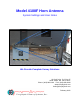


Geophysical Survey Systems, Inc. Model 4108F Antenna
System Settings and User’s Notes
MN34-550 Rev A
5
Quick Setup Procedure SIR-20
1. Connect the transducer cable from the SIR-20 (Channel 1) to the Model 4108F antenna.
2. Connect the power supply to the SIR-20.
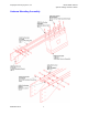
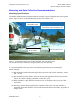
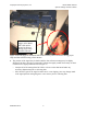
3. Connect the Model 10F marker cable to the marker connector on the SIR-20, shown in
Figure 4. The SIR-20 will not operate with a horn antenna without this cable attached.
Figure 3. Location of attachment of Model 10F marker/transmit switch cable.
4. Turn on the SIR-20 and wait until it is booted-up.
5. Double-click on the SIR-20 Desktop shortcut.
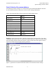
6. Press to recall a saved project for the Model 4108F antenna.
• First time users may want to select the “1GHz Horn Free Run” project from the folder
“Fixed SIR-20 Setups.”
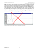
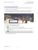
7. Press to run the project. Be sure to keep the red “trigger” pressed on the handle of the
model 10F marker/transmit switch cable as shown in Figure 4. If the red trigger is released at
any time during data collection, data collection will be paused after 2 seconds and the data
file will be closed after 10 seconds.
Attachment location of
Model 10F
marker/transmit switch