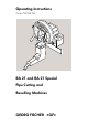
Operating Instructions Code 790 044 762 RA 21 and RA 21 Special Pipe Cutting and Bevelling Machines GEORG FISCHER +GF+
These operating instructions are part of machine no.: ......................... All rights retained, in particular the rights to reproduction, dissemination and translation. Copying or reproduction in any form (print, photocopy, microfilm or data acquisition) require written permission from Georg Fischer Rohrverbindungstechnik GmbH.
Table of Contents Page 0 About these operating instructions 1 1 Notes on safety 2 2 Description of the pipe cutter 4 3 Features and scope of application of the pipe cutter 5 4 Technical specifications 7 5 Commissioning 5.1 Checking the scope of delivery 5.2 Transporting and assembling the pipe cutter 8 8 6 Operation 6.1 Fitting the saw blade / additional cutter 6.2 Adjusting the pipe diameter 6.3 Adjusting the additional cutter 6.4 Using stops 6.5 Cutting the pipe 6.
II GEORG FISCHER +GF+
0 About these operating instructions The symbols used in this manual are explained here to help you quickly understand the operating instructions and use them effectively. Symbols Note on safety This general hazard symbol accompanies passages of text which you should read and understand under all circumstances. By failing to do so you could endanger yourself and others. Important information Passages of text which convey important information are accompanied by this symbol.
1 Notes on safety The RA 21/RA 21 Special Pipe Cutting and Bevelling Machine (referred to as a pipe cutter in the following) is a state-of-the-art machine. Using it for purposes other than those described in this manual may cause injury to the user or to others. It may also damage the machine or other equipment. Therefore: º Always ensure that the machine is in good working order and always comply with these notes on safety.
Working with safety in mind "Make your contribution to safety at the workplace." Report any unusual behaviour on the part of the machine to the person in charge immediately. Always work with safety in mind. º Wear safety goggles during cutting and bevelling operations. º Switch the RA 21 (S) off after completing each stage of work and allow the machine to run a stop. º Disconnect from the mains before cleaning the pipe cutter. The cutter and saw blade may cause injury.
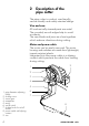
2 Description of the pipe cutter The pipe cutter is a robust, user-friendly, service-friendly and safety-oriented design. Vise and saw All mechanically stressed parts are metal. The rounded, smooth edges help to avoid accidents. The saw blade and jaws are close togethers which reduces vibrations during cutting. Motor and power cable The motor can be easily removed. The motor housing and switches are made from lightweight, impact-resistant plastic.
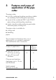
3 Features and scope of application of the pipe cutter The pipe cutter º is a fully configured working machine suitable for workshop and building site operation; º is part of the combined KM 2 and GTM 2 pipe cutting and threading machines; º works using the safety-enhancing principle: stationary pipe, rotating tool. The pipe cutter is suitable for º cutting and º bevelling pipes. The cut pipes are free from burr, so no deburring (in- or outside) is required. This reduces the risk of corrosion.
The following materials can be used: º steel, black or galvanised º chrome and stainless steel (up to 2.5 mm wall thickness) º aluminium º non-ferrous metals (e.g. copper, brass) º plastics (PE, PP, PVDE, PVC) Other materials on request. Do not use cast pipes with glass-hard surfaces (GG).
4 Technical specifications Manufacturer Georg Fischer Rohrverbindungstechnik GmbH D-78224 Singen Dimensions 300 x 450 x 300 mm Weight (incl. vise) 34 kg Power 550 W Protection class Totally insulated in accordance with Class II DIN VDE 0740 Speed 180 rpm Versions 1-phase AC 110 ... 120 V, 50/60 Hz 230 ... 240 V, 50/60 Hz Sound pressure level at the workplace at idle: approx. 82 dB (A) under load: approx.
5 Commissioning 5.1 Checking the scope of delivery Check all parts of the delivery for completeness and transport damage. Please report missing parts or transport damage to the support immediately.
5.2 Transporting and assembling the pipe cutter Transport Disconnect from the power supply before transporting, mounting or dismounting and allow the machine to run a stop. Mounting the quick mounting base plate The pipe cutter with the vise is mounted either º on the quick mounting base plate, or º on the quick mounting base plate (special accessory) with clamps. !Mark and punch the bolt holes on the work bench. Use the quickmounting baseplate as a template. !Drill 13 mm Ø holes.
6 Operation 6.1 Fitting the saw blade / additional cutter Disconnect the mains plug before fitting or changing the tool. The saw blade/additional cutter must be free from chips and dirt. Use only original Georg Fischer saw blades and cutters. The inscription on the saw blade (1) must always face the pipe cutter. Observe sign for saw blade guard. 1 Preparatory work !Loosen the locking screw (1). !Turn the pipe cutter upwards 180° clockwise. !Tighten the locking screw (1).
Fitting the saw blade 1 2 5 4 3 !Mount the following on the shaft (1): º saw blade (3) º clamping disk (4) code RA 21: 790 041 188 code RA 21 S: 790 044 192 !Tighten the nut (5) by turning counterclockwise. Left-hand thread. !Loosen the locking screw (2). !Turn the pipe cutter clockwise back down into its home position.
6.2 Adjusting the pipe diameter Threaded pipes to DIN 2440 !Release the lever (1). !Select pipe diameter on the scale (3). !Set the red mark on the left side of the stop (2) to the corresponding number. !Tighten the lever (1). open 2 3 /2 /4 1 1/2 3/4 3/8 1 1/4 2 11 11 All other types of pipe 12 1 11 2 /2 11 /4 1 3/4 1/2 3/8 1/4 2 !Insert the pipe in the vise. !Move the pipe almost up to the saw blade. !Tighten the pipe in the vise.
6.3 Adjusting the additional cutter Simultaneous cutting and bevelling of steel pipes up to a wall thickness of 4.5 mm is possible. 1 /2 2 Bevel OK 1 3/4 1/2 3/8 !Insert the pipe in the vise. !Move the pipe almost up to the additional cutter. !Clamp the pipe in the vise. !Release the lever (1) and set the stop (2) to position 2". Do not tighten. !Raise the motor of the pipe cutter as if to start cutting, until the cutter covers the wall of the pipe. !Tighten the lever (1).
6.4 Using stops Length gauge up to 250 mm !Mount the length gauge (1). !Swing the stop (2) in to the middle of the pipe and engage. !Release the cross knob (3). !Set to the desired length. Use the scale. !Tighten the cross knob. !Push the pipe forwards up to the stop and clamp. !Swing the stop clear. !Cut the pipe. 2 3 1 Length gauge over 250 mm !Mount the length gauge (1). !Swing the stop in to the middle of the pipe. !Use a yardstick to extend the stop to the desired length.
!Tighten the clamp. !Push the pipe up against the stop and clamp. !Swing the stop out and push all the way back. !Cut the pipe. !For the next cut, extend the stop and swing into place clockwise.
6.5 Cutting the pipe Cut thin-walled chrome and stainless steel pipe up to 1.5 mm wall thickness only with RA 21 Special. Put on safety goggles before cutting. !Connect the pipe cutter to the mains. !Apply saw blade lubricant to the saw blade teeth. Repeat the lubrication every three cuts. If in contact with drinking water or foodstuffs, use only Georg Fischer lubricating gel. !Mark the cutting location on the pipe. !Insert the pipe in the vise. !Push the marked cutting location over the saw blade.
!Switch on the saw motor. Press the on/ off switch (1) and the locking button (2). 1 2 1 3 /4 11 1 3/4 1/2 3/8 1/4 2 /2 11 !Carefully turn the pipe cutter clockwise until the wall of the pipe has been pierced through. !Continue to turn rapidly until the pipe has been cut off and the marks (3) on the slide housing and vise housing are aligned. !Turn the pipe cutter back into its home position. !Switch off the saw motor. Press the on/ off switch (1) again.
6.6 Cutting and bevelling the pipe This procedure combines cutting and bevelling of the pipe. When cutting and bevelling simultaneously, turn the pipe cutter more slowly around the pipe that you would for cutting alone, as two tools are used at the same time. Put on safety goggles before cutting. !Connect the pipe cutter to the mains. !Apply saw blade lubricant to the saw blade teeth/cutting surface. Repeat the lubrication every three cuts.
!Switch on the saw motor. Press the on/ off switch (1) and the locking button (2). 1 2 1 3 /4 11 1 3/4 1/2 3/8 1/4 2 1 2 1/ !Carefully turn the pipe cutter clockwise until the wall of the pipe has been pierced through. !Continue turning rapidly until the pipe has been cut off and the marks (3) on the slide housing and vise housing are aligned. !Turn the pipe cutter back into its home position. !Switch off the saw motor. Press the on/ off switch (1) again.
7 Maintenance Disconnect the mains plug before doing maintenance work. Interval Activity every week Remove the saw blade and brush off chips. Oil the four locations marked by the arrows. Check the oil level of the gear and top up if necessary. º every time the cutter is cleaned º every tool change Do not use compressed air to clean the area at the end of the shaft marked with an arrow as the rotary shaft seal may otherwise be damaged by chips. Use a cloth or brush to clean the end of the shaft.
Interval Activity after the first 150 hours of operation (or after 3 months, whichever is sooner), then every 1000 hours of operation (or every year) Fill with gear oil up to the threaded hole.
8 What to do if ...? Problem Cause Remedy Pipe cutter will not turn. Locking screw tightened. Loosen locking screw. Wrong pipe diameter set. Set pipe diameter correctly. Saw blade is not cutting and is slipping. Nut on saw blade shaft not tight enough. Tighten nut. Saw blade is not cutting. Saw blade wrong way round. Fit saw blade correctly. Inscription on saw blade must face the pipe cutting machine (see chapter 6). Pipe is not being cut concentrically. Pipe cutter not flanged on.
Service / after-sales service Spare parts: see separate spare parts list. Separate service instructions are available for the elimination of faults. Alternatively, contact your local Georg Fischer agent. A list of addresses is provided on the back cover of this manual. Please quote the following data: º Cutter type: RA 21/RA 21 Special º Machine number: see nameplate. The technical data are not binding. They are not warranted characteristics and are subject to change.
GEORG FISCHER +GF+ A Georg Fischer Rohrleitungssysteme GmbH, Sandgasse 16, 3130 Herzogenburg, Tel. +43(0)2782/8 56 43-0, Fax +43(0)2782/8 56 64, office@georgfischer.at, www.georgfischer.at AUS George Fischer Pty Ltd, 186-190 Kingsgrove Road, Kingsgrove NSW 2008, Tel. +61(0)2/95 54 39 77, Fax +61(0)2/95 02 25 61, sales@georgefischer.com.au, www.georgefischer.com.au B/L Georg Fischer NV/SA, Digue du Canal 109-111 – Vaartdijk 109-111, 1070 Bruxelles/Brüssel, Tél.