
Instructions / Assembly

INSTALLATION INSTRUCTIONS
Item#P1591-691 (Rev. 2021/05/28)
READ AND SAVE THESE INSTRUCTIONS
W A R N I N G ! S H U T P O W E R O F F AT F U S E O R C I R C U I T B R E A K E R .
AVERTISSEMENT! COUPER LE COURANT AU NIVEAU DES FUSIBLES OU DU DISJONCTEUR.
IMPORTANT: FIXTURE SHOULD BE INSTALLED BY
A QUALIFIED ELECTRICIAN TO ENSURE PROPER
WIRING AND INSTALLATION.
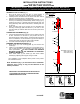
Fig. 1
Fig. 2
ASSEMBLING THE FIXTURE (Fig. 1)
1.
Shut off the power at the fuse box or circuit breaker. If
necessary, remove old fixture, including mounting hardware.
2.
Carefully remove the fixture from the carton and check that all
parts are included as shown in the illustration.
3.
Determine the desired hanging height and thread rods (F1, F2
and F3) to all thread (E) of Fixture Body. Attach canopy (C
) by
screwing onto rod (F1). Carefully pass wires through each rod
during assembly. Note: Remove all thread
, if installing with one
6” rod only.
4. Attach mounting plate (A) to junction box (not included)
with
mounting screws (B) (Size: #8-
32N*L0.5”). The side of the
mounting plate (A) marked
“GND” and two convex points must
face out.
CONNECTING THE WIRES (Fig. 2)
5.
Connect the electrical wires as shown in fig 2, making sure that
all wire connectors are secured. If your junction box has
a
ground wire (green or bare copper), connect the fixture’s ground
wire to it. Otherwise, connect the fixture’s ground wire directly to
the mounting plate (A) using the green screw provided.
6. Tuck wire connectors neatly into junction box.
FINISHING THE INSTALLATION (Fig.1)
7. Slide canopy (C) over mounting pla
te (A) and secure with
screws (D).
8. Install (1) one candelabra base bulb (H)
up to 60 watts each or
CFL or LED equivalent (not included) in accordance with the
fixture specification. — DO NOT EXCEED THE MAX
IMUM
WATTAGE RATING! (NE PAS DEPASSER LA PUISSANCE
NOMINALE MAXIMALE!).
9. Place
metal shade (J) into holder (G) and secure shade
assembly by adjusting each support rod (I) in holder.
Your installation is now complete. Return power to the junction
box and test the fixture.
Note: Illustration (Fig. 1
) on this manual is for installation
purposes only. It may or may not be identical to the
fixture purchased.
LA-3411E
FIXTURE
WIRES
Black or
Smooth
HOUSE
WIRES
Black
(Hot)
FIXTURE
WIRES
White or
Ribbed
H
OUSE
WIRES
White
(Neutral)
FIXTURE
WIRES
Bare
Copper
(Ground)
HOUSE
WIRES
Green
(Ground)
Set
#
A
-
0
21
-
118DH
-Mounting plate
-Ground screw
-Mounting screw*2
Rod# W30-1-66A*1(F1)
W30-1-66A*2(F2)
W30-H-66A*1(F3)
A
B
C
D
E
F1
F2
F3
H
I
G
J