
User's Manual
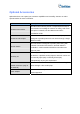
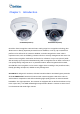
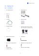
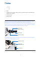
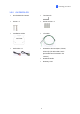
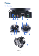
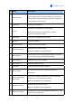
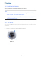
Table Of Contents
- Contents
- Note for Connecting to GV-DVR / NVR / VMS
- Note for Recording
- Note for Installing Camera Outdoor
- Optional Accessories
- Chapter 1 Introduction
- Chapter 2 Getting Started
- Chapter 3 Accessing the Live View
- Chapter 4 Administrator Mode
- Chapter 5 Face Recognition
- 5.1 Features
- 5.2 Installation Flowchart
- 5.3 Ideal Camera Position
- 5.4 Adjusting Illumination
- 5.4.1 Daytime
- 5.4.2 Nighttime
- 5.4.3 Low Illumination (WDR)
- 5.5 Enrolling Face Data
- 5.5.1 Photo Requirements
- 5.6 Face Recognition Basic Settings
- 5.6.1 Settings
- 5.6.2 License
- 5.6.3 Management
- 5.6.4 Events
- 5.6.4.1 Searching for log data
- 5.6.4.2 Enrolling Faces
- 5.6.4.3 Synchronizing Face Databases
- 5.6.5 Trigger Area
- Chapter 6 Recording and Playback
- Chapter 7 Advanced Applications
- Chapter 8 DVR / NVR / VMS Configurations
- Chapter 9 Smart Device Connection
- Appendix

Getting Started
2
No. Name Description
1 LED Indicators
(top) turns on when the power is on and
The power LED
turns off when there is no power supply. The status LED
(bottom) turns on when the system operates normally and
turns off when an error occurs.
2 Audio Out
Currently not functional.
3 Line In
e for audio input.
rnal
Connects to a microphon
Note: This interface only works with an exte
microphone with power supply.
4 LAN / PoE r PoE. Connects to a 10/100 Ethernet o
5 DC 12V Connects to power.
6 Rotational Screw camera. Loosens to rotate the
7 Conduit Connector
.
0-FR.
Waterproofs the Ethernet cable
Note: Not available for GV-FD870
8 Default Button
ngs. For details, Resets the camera to factory default setti
see 7.2 Restoring to Factory Default Settings.
9 Focus Screw Adjusts the focus of the camera.
10 Zoom Screw Zoom the camera in or out.
11 Tilt Screw Loosens the screw to tilt the camera.
12 I/O Connector
ee 1.6 I/O Connects to I/O devices. For details, s
Connectors.
13
Built-in Microphone
built-in microphone to record sound. For
Connectors
Connects to a
details, see 1.5 Connecting the Camera.
Note: Not available for GV-FD8700-FR.
14 Conduit Connector
FR.
Waterproofs the audio / I/O wires.
Note: Not available for GV-FD8700-
15 Memory Card Slot
XC/UHSI, Class
10) to store recording data.
Contains a micro-SD card (SD/SDHC/SD
8