
User's Manual
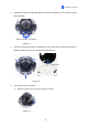
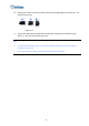
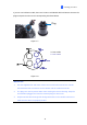
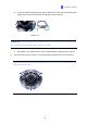
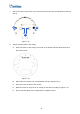
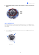
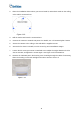
Table Of Contents
- Contents
- Note for Connecting to GV-DVR / NVR / VMS
- Note for Recording
- Note for Installing Camera Outdoor
- Optional Accessories
- Chapter 1 Introduction
- Chapter 2 Getting Started
- Chapter 3 Accessing the Live View
- Chapter 4 Administrator Mode
- Chapter 5 Face Recognition
- 5.1 Features
- 5.2 Installation Flowchart
- 5.3 Ideal Camera Position
- 5.4 Adjusting Illumination
- 5.4.1 Daytime
- 5.4.2 Nighttime
- 5.4.3 Low Illumination (WDR)
- 5.5 Enrolling Face Data
- 5.5.1 Photo Requirements
- 5.6 Face Recognition Basic Settings
- 5.6.1 Settings
- 5.6.2 License
- 5.6.3 Management
- 5.6.4 Events
- 5.6.4.1 Searching for log data
- 5.6.4.2 Enrolling Faces
- 5.6.4.3 Synchronizing Face Databases
- 5.6.5 Trigger Area
- Chapter 6 Recording and Playback
- Chapter 7 Advanced Applications
- Chapter 8 DVR / NVR / VMS Configurations
- Chapter 9 Smart Device Connection
- Appendix

B. Unplug the conduit connector inside the housing and disintegrate the connector. You
should have
3 parts:
Figure 1-6
C. Thread the audio wires and I/O wires through the conduit entry and then through
parts 1, 2, and 3 of the conduit connector.
Tip:
1. To make the threading easier, it is recommended to thread the wires in the order
2. Use a pair of pliers to help you pull the wires through the camera.
described in Step 4-C.
11