
User's Manual
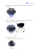
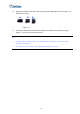
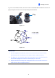
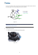
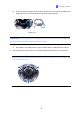
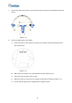
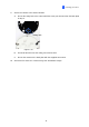
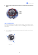
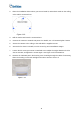
Table Of Contents
- Contents
- Note for Connecting to GV-DVR / NVR / VMS
- Note for Recording
- Note for Installing Camera Outdoor
- Optional Accessories
- Chapter 1 Introduction
- Chapter 2 Getting Started
- Chapter 3 Accessing the Live View
- Chapter 4 Administrator Mode
- Chapter 5 Face Recognition
- 5.1 Features
- 5.2 Installation Flowchart
- 5.3 Ideal Camera Position
- 5.4 Adjusting Illumination
- 5.4.1 Daytime
- 5.4.2 Nighttime
- 5.4.3 Low Illumination (WDR)
- 5.5 Enrolling Face Data
- 5.5.1 Photo Requirements
- 5.6 Face Recognition Basic Settings
- 5.6.1 Settings
- 5.6.2 License
- 5.6.3 Management
- 5.6.4 Events
- 5.6.4.1 Searching for log data
- 5.6.4.2 Enrolling Faces
- 5.6.4.3 Synchronizing Face Databases
- 5.6.5 Trigger Area
- Chapter 6 Recording and Playback
- Chapter 7 Advanced Applications
- Chapter 8 DVR / NVR / VMS Configurations
- Chapter 9 Smart Device Connection
- Appendix

Getting Started
2
If you use cat 5 Ethernet cable, there are 5 holes each labeled with its diameter. Remove th
plugs and push the wires to
e
the corresponding hole listed below:
Plug
Figure 1-7
1.
9 mm: DIDO
Figure 1-8
IMPORTANT:
1. Use the supplied ruler and leave at least 14 cm of I/O wires and 10 cm of audio
wires between their connectors on the camera and the conduit connector.
2. The plugs are used to prevent water from entering the camera housing. Keep the
unused holes plugged and save the removed plugs for future use.
3. Only thread the wires through their designated holes on the conduit connector to
make sure the wires are properly sealed.
3.2 mm: Audio
12