
User's Manual
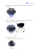
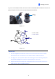
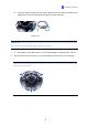
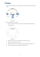
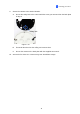
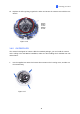
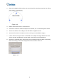
Table Of Contents
- Contents
- Note for Connecting to GV-DVR / NVR / VMS
- Note for Recording
- Note for Installing Camera Outdoor
- Optional Accessories
- Chapter 1 Introduction
- Chapter 2 Getting Started
- Chapter 3 Accessing the Live View
- Chapter 4 Administrator Mode
- Chapter 5 Face Recognition
- 5.1 Features
- 5.2 Installation Flowchart
- 5.3 Ideal Camera Position
- 5.4 Adjusting Illumination
- 5.4.1 Daytime
- 5.4.2 Nighttime
- 5.4.3 Low Illumination (WDR)
- 5.5 Enrolling Face Data
- 5.5.1 Photo Requirements
- 5.6 Face Recognition Basic Settings
- 5.6.1 Settings
- 5.6.2 License
- 5.6.3 Management
- 5.6.4 Events
- 5.6.4.1 Searching for log data
- 5.6.4.2 Enrolling Faces
- 5.6.4.3 Synchronizing Face Databases
- 5.6.5 Trigger Area
- Chapter 6 Recording and Playback
- Chapter 7 Advanced Applications
- Chapter 8 DVR / NVR / VMS Configurations
- Chapter 9 Smart Device Connection
- Appendix

7. Sort out the wires at the back. You can have the wires come out from positions A and B or
from C.
A
B
C
Figure 1-12
8. Secure the back plate to the ceiling.
A. Paste the sticker to the ceiling. The arrow on the sticker indicates the direction that
the camera faces.
Figure 1-13
B. Drill 4 holes for screws. The recommended ones are indicated as ‘1’.
C. Insert the screw anchors to the 4 holes.
. Drill holes A & B or only hole C for sorting out the wires according to Figure 1-12.
E. Secure the back plate to the ceiling with the supplied screws.
D
15