
User's Manual
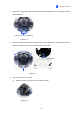
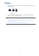
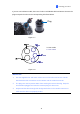
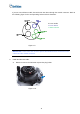
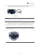
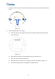
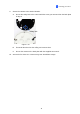
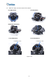
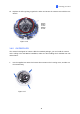
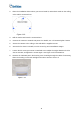
Table Of Contents
- Contents
- Note for Connecting to GV-DVR / NVR / VMS
- Note for Recording
- Note for Installing Camera Outdoor
- Optional Accessories
- Chapter 1 Introduction
- Chapter 2 Getting Started
- Chapter 3 Accessing the Live View
- Chapter 4 Administrator Mode
- Chapter 5 Face Recognition
- 5.1 Features
- 5.2 Installation Flowchart
- 5.3 Ideal Camera Position
- 5.4 Adjusting Illumination
- 5.4.1 Daytime
- 5.4.2 Nighttime
- 5.4.3 Low Illumination (WDR)
- 5.5 Enrolling Face Data
- 5.5.1 Photo Requirements
- 5.6 Face Recognition Basic Settings
- 5.6.1 Settings
- 5.6.2 License
- 5.6.3 Management
- 5.6.4 Events
- 5.6.4.1 Searching for log data
- 5.6.4.2 Enrolling Faces
- 5.6.4.3 Synchronizing Face Databases
- 5.6.5 Trigger Area
- Chapter 6 Recording and Playback
- Chapter 7 Advanced Applications
- Chapter 8 DVR / NVR / VMS Configurations
- Chapter 9 Smart Device Connection
- Appendix

2. Place the installation sticker where you want to install it, and make 3 marks on the ceiling
or the wall for screw anchors
Figure 1-18
3. Drill the marks and insert the screw anchors.
4. Connect the ca etwork and power. For details, see 1.5 Connecting the Camera. mera to n
5. Secure the camera to the ceiling or the wall with the supplied screws.
6. Access the live view. For details, see 2.3 Accessing Your Surveillance Images.
7. Loosen the tile screw, pan screw or rotational screw. Adjust the angles based on the live
view as needed, and tighten the screws again. See Figure 1-15 for illustrations.
8. Remove the indicated part in the housing cover for wiring through the cables if necessary.
Place the housing cover back and tighten the three screws to secure it.
Figure 1-19
19