Quick Start Guide GV-VMS Thank you for purchasing GV-VMS. This guide is designed to assist the new user in getting immediate results from the GV-VMS. For advanced information on how to use the GV-VMS, please refer to GV-VMS User's Manual online. © 2014 GeoVision Inc. All rights reserved.
© 2014 GeoVision, Inc. All rights reserved. Under the copyright laws, this manual may not be copied, in whole or in part, without the written consent of GeoVision. Every effort has been made to ensure that the information in this manual is accurate. GeoVision, Inc. makes no expressed or implied warranty of any kind and assumes no responsibility for errors or omissions. No liability is assumed for incidental or consequential damages arising from the use of the information or products contained herein.
Contents Chapter 1 Introduction.........................................................................1 1.1 License.................................................................................................................... 1 1.2 Options.................................................................................................................... 2 1.3 Minimum System Requirements .............................................................................. 3 1.4 Minimum Network Requirements.
Chapter 7 Other Important Features ................................................ 37 7.1 Setting Up I/O Functions ........................................................................................37 7.2 Setting Up Schedules .............................................................................................39 7.3 Setting Up E-mail Alert Notifications .......................................................................
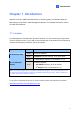
1 Introduction Chapter 1 Introduction Welcome to the GV-VMS Quick Start Guide. In this quick guide, you will learn about the basic settings of GeoVision Video Management System. For complete instructions, refer to GV-VMS User’s Manual. 1.1 License GV-VMS supports connection with up to 64 IP devices. You can connect up to 32 channels of GV-IP Devices for free. If you need to connect more than 32 channels of GV-IP Devices or connect with third-party IP devices, license is required.
1.2 Options The following optional devices are available to expand your GV-VMS’s capabilities and versatility. Contact your dealer for more information. Optional Devices Description Internal USB Dongle The USB dongle can provide the Hardware Watchdog function to the GV-VMS by restarting the computer when Windows crashes. You need to connect the dongle internally on the motherboard.
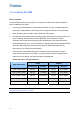
1 Introduction 1.3 Minimum System Requirements Below are the minimum PC requirements needed to connect GV-VMS with 32 and 64 channels of GV and 3rd party IP cameras (dual streams). GV-VMS (Up to 32 Channels) GV-VMS Pro (Up to 64 Channels) OS 64-bit Windows 7 / 8 / 8.1 / Server 2008 R2 / Server 2012 R2 CPU 4th Generation i3-4130, 3.4 GHz 4th Generation i7-4770, 3.4 GHz Memory 4 GB RAM 8 GB RAM 1.
1.5 Installing GV-VMS Before You Start For optimal performance of your system, it is important to follow these recommendations before installing the GV-VMS: • It is strongly recommended to use separate hard disks. One is for installing Windows OS and GV-VMS software, and the other is for storing recorded files and system logs. • When formatting the hard disks, select NTFS as the file system. • GV-VMS is a multi-channel video recording system.
1 Introduction The frame rate limit is based on the resolution of video sources. The higher video resolutions, the lower frame rates you can assign to a single hard disk. In other words, the higher frame rates you wish to record, the more hard disks you need to install. For the information of recording frame rates, you may consult the user’s manual of the IP camera that you wish to connect to. Installing GV-VMS 1.
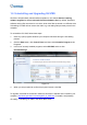
1.6 Uninstalling and Upgrading GV-VMS GeoVision will periodically release software updates on our website. Before installing software upgrade, be sure to uninstall GeoVision Software first. By default, GeoVision software and log files are stored on one drive, while video files are stored on a different drive. Uninstalling GV-VMS will not remove the video, log, and setting files previously saved in the computer. To uninstall the GV-VMS, follow these steps: 1.
1 Introduction 1.7 Running GV-VMS 1. To start the system, double-click the GV-VMS icon on desktop or in the folder where you have installed it. 2. Type your login information. Figure 1-4 3. Click E-Mail List to set up an e-mail address so that you can recover a forgotten password when needed. 4. Click OK. The main screen of GV-VMS and a dialog box appears. 5.
In the main screen of GV-VMS, the main setting buttons are located in the top-right corner. When logging in for the first time, the Automatic Setup dialog box will appear to help you quickly add cameras to the GV-VMS. Refer to the next section for details.
2 Getting Started Chapter 2 Getting Started 2.1 Adding IP Cameras to GV-VMS When logging in for the first time after GV-VMS is installed, the Automatic Setup dialog box appears automatically. Follow the steps below to add IP cameras. 1. Click Automatic Setup to see the list of IP cameras detected on the LAN. Figure 2-1 2. The default login information for cameras is admin / admin. Double-click the camera to type different ID and password in the dialog box below if needed.
3. Make sure the cameras you want to add are selected and click Apply. The cameras added are now listed in the IP Device List. Figure 2-3 Status icons available: Connected The camera is connected. Connecting GV-VMS is trying to connect to the camera. Connection Failed Unable to connect to the camera. Place the cursor on the red icon to see the error message. Inactive Camera The camera is inactive. Click the checkbox to connect. Started Monitoring The camera is under monitoring.
2 Getting Started 2.2 Accessing Camera Live View After adding cameras, you can access camera live view by dragging the camera in the Content List to the live view grid. 1. Click Home appears. 2. Click Camera in the content list to see the list of cameras added. 3. Drag the cameras to the live view grid. , select Toolbar , and select Content List . The Content List Figure 2-4 For details, see Chapter 4 Live View in this Quick Start Guide.
2.3 Start Monitoring After setting up cameras and the live view, be sure to start monitoring the cameras to activate the following functions. • Recording (See Section 3.1) • Video Analysis (See Chapter 5) • I/O Applications (See Section 7.1) To start monitoring on connected cameras, click Toolbar Start All Monitoring or select individual cameras. , select Monitor , and select Figure 2-5 To see how to access recorded videos, refer to Chapter 6 Video Playback and Backup in this Quick Start Guide.
3 Camera Setup Chapter 3 Camera Setup 3.1 Configuring Recording Settings After the cameras are added, you can configure the recording settings. Under Home , click Configure select Toolbar Setting. This dialog box appears. , , select System Configure and click Record Figure 3-1 1. Enable the Recycle function. The oldest events will be deleted when the free space of the storage drive falls below the recycle threshold specified in step 4 below. This setting will be applied to all cameras. 2.
4. Click the Arrow button next to Storage to specify where to store the recorded videos and adjust the recycle threshold. 5. You can set different recording frame rates for motion and non-motion recordings. In Round-the-Clock mode, the camera will use the frame rate setting in 5a for non-motion events and 5b for motion events. a. Define non-motion events as General or Urgent Event under Video Record Frame Rate. b.
3 Camera Setup 3.2 Configuring Camera Settings To configure camera settings such as codec and frame rates, click the Setup button of an > Toolbar > Configure > Camera active camera in the IP Device List (Home Install). The settings available vary depending on the camera’s firmware and whether the camera is connected. There are three setup dialog boxes in the left menu of the camera’s setting dialog box: Video Setting, Audio Setting, and General Setting.
[Audio Setting] In Audio Setting, you can enable audio functions for live view and recording, which are disabled by default. Figure 3-3 1. To enable audio in camera live view, select Wave Out. 2. To enable audio recording, select Rec Audio and then select By Sensitivity or Roundthe-Clock. Note: After Wave Out is enabled here, you can enable audio on the live view of the camera and select Set to Wave Out.
3 Camera Setup [General Setting] In General Setting, you can configure Network timeout setting, on-demand display, live view frame rate, and recording frame rate settings. Set live view frame rate Set recording frame rate Figure 3-4 1. Under Live view frame rate control (Main / Sub Stream), you can set the live view frame rate. • When using MJPEG, every frame is a key frame, so you can specify the number of key frames to decode for live view. • When using H.
Note: 1. The GOP setting can be configured in the Video Setting dialog box (Figure 3-2). A GOP of 30 means that there is 1 key frame for every 30 frames, so an IP device with a frame rate of 30 fps will have 1 key frame per second. 2. You can change the camera’s main stream and sub stream to H.264 or MJPEG in the Video Setting dialog box (Figure 3-2). After changing codec, you need to click OK to apply the change before switching to the General Setting.
4 Live View Chapter 4 Live View 4.1 Arranging Live View Layouts Follow the steps below to create new live view layouts. 1. In the Content List (Home >Toolbar > Content List ), click Layout. Figure 4-1 2. To add a layout, click the Add button and click Add Layout. This dialog box appears. Figure 4-2 3. Name the new layout.
4. You can select an existing layout under Layout Setup or specify the number of live views in each row and column of the grid. 5. To create your own layout, a. Select Customize and click OK. b. Click the Reset button to select a dimension for the grid. Figure 4-3 c. Select multiple squares and click the Merge button to create a larger square. Figure 4-4 6. Click OK when you are done. A message appears. Click Yes if you want to automatically assign the cameras to the new layout.
4 Live View 4.2 Functions on the Live View Place the mouse cursor on the camera live view to see the icons below. Figure 4-5 Icons Functions Instant Play Plays back the video recorded in the last 10 seconds, 30 seconds, 1 minute, or 5 minutes. Snapshot Captures a snapshot of the current live view. Tools Includes the following options: • Monitor: Starts monitoring the camera. • Talk Back Toggle: Talks to the surveillance site from the PC. Only one camera can be enabled at a time.
The live view screen can be controlled using the actions below. Actions Functions Mouse scroll Zooms in or out on the live view. Double-click Displays the live view in full screen.
4 Live View 4.2.1 Zoom Window You can designate a Zoom Window to quickly see a close-up view of the camera image without changing the live view layout. 1. In the Content List, select Layout, click Windows and drag Zoom Window to a live view grid.
2. Move the mouse cursor to a camera live view and click the Zoom button right corner. The camera live view is displayed in the Zoom Window. in the top- Zoom Figure 4-7 3. To remove the camera from the Zoom window, place the cursor on the live view, click the Tools icon and select Close. To change the live view grid back to a normal window, repeat this step again to close the Zoom Window.
4 Live View 4.2.2 Scan Window You can assign multiple cameras to a Scan Window, and each camera will be shown in sequence for the Scan Interval specified. 1. In the Content List, select Layout and drag Scan Window to a live view square. 2. Drag multiple cameras into the Scan Window.
3. Move the cursor to the Scan Window, click the Tools icon , and select Properties. Figure 4-9 4. To adjust the order of a camera, click the Up and Down arrows. 5. To specify how many seconds to show the live view, click and adjust the Scan Interval of each camera. In the figure above, each camera will be shown for 5 seconds.
4 Live View 4.2.3 Focus View and PIP Focus View You can create up to 7 close-up views per camera and place these created close-up views inside live view grid. This function is not supported for Fisheye Cameras and PTZ Cameras. 1. In the Content List, right-click a camera and select Focus View Setup. A dialog box appears. Figure 4-10 2. Click Enable and draw a box on the camera view to create a focus view. You can create multiple focus views if needed. 3.
5. You can now drag the focus views to live view grids. Figure 4-11 PIP View (Picture-in-picture) 1. You can zoom in on a camera by placing mouse cursor on its live view and scrolling the mouse. An inset window appears in the camera view with a navigation box inside. Figure 4-12 2. Move the navigation box around in the inset window to have a close-up view of the selected area.
4 Live View 4.3 Setting Up Fisheye Cameras If you have added a fisheye camera, follow the steps below to access fisheye functions. 1. In the Content List, drag the entire fisheye camera (ex: Camera5) to the live view grid to see the circular source image or expand the camera and drag one of the dewarped fisheye images (ex: Quad View) to the live view grid. Circular source image Dewarped fisheye image Individual views of the dewarped fisheye image Figure 4-13 2.
3. Right-click the camera view and select Fisheye Option to access the fisheye functions. Figure 4-14 For details on the fisheye functions, see Fisheye View, Chapter 3, GV-VMS User Manual.
4 Live View 4.4 Setting Up PTZ Cameras If you have added a PTZ camera, follow the steps below to enable PTZ functions. 1. Move the cursor to the camera live view and click the Tools button 2. Click PTZ Control to enable PTZ function. 3. Move the cursor to the live view to see the PTZ control panel. . Figure 4-15 Note: The PTZ control panel is hidden when live view resolution is less than 240 x 180. 4.
Chapter 5 Video Processing GV-VMS offers a number of video processing functions. To configure video processing functions, follow the steps below. 1. Click Home , select Toolbar , click Configure Process. This dialog box appears. and then select Video Figure 5-1 2. Select a function under Video Analysis. 3. In the Camera List, select the camera(s) you want to configure. 4. Click the Setting button to access the configuration page. 5.
5 Video Processing The following Video Processing functions will only be enabled when you start monitoring on the cameras.
Chapter 6 Video Playback and Backup 6.1 Playing Back Recorded Videos 1. To access recorded videos, click the ViewLog icon 2. Open the Content List by clicking Toolbar 3. Click Layout in the Content List, click the Add button in the top-right corner. and selecting Content List . , and select Add Layout to create a new layout or select Import from Live to import existing layouts from live view. 4.
6 6. Video Playback and Backup Click on the timeline to select a time with video recordings. You can scroll the mouse to zoom in and out on the timeline. • Blue areas represent videos recorded in round-the-clock mode. • Orange areas represent motion and other alarm events. Figure 6-3 7. Use the playback control buttons to play back recordings. Place the cursor on the buttons to see the name of the function.
6.2 Backing Up Recorded Videos 1. In ViewLog, click Toolbar , select Tools and select Backup. This dialog box appears. Figure 6-5 2. Click Add time frame to select the time period and the cameras you want to back up and click OK. 3. Select a media to back up the recorded files using Hard Disk, CD / DVD/ BD or OSBurning. The supported software for burning to CD / DVD / BD is Nero Burning Rom version 9 or before. 4.
7 Other Important Features Chapter 7 Other Important Features 7.1 Setting Up I/O Functions Follow the steps below to set up I/O devices on GV-VMS: 1. Click Home , select Toolbar , click Configure , click Accessories (if available), click I/O Device (if available) and then select I/O Device Setup. This dialog box appears. Figure 7-1 Note: The Accessories option only appears when GV-Keyboard or GV-Joystick has been set up on the GV-VMS.
5. After the I/O devices are added, select Toolbar , click Configure , click Accessories (if available), click I/O Device and select I/O Application Setup. This dialog box appears. Figure 7-2 6. Select an input and specify the actions to take when the input is triggered. 7. Click OK to apply the settings. 8. To activate I/O functions, click Home , select Toolbar then click I/O Monitoring or Start All Monitoring.
7 Other Important Features 7.2 Setting Up Schedules You can create a schedule to enable and disable recording, video analysis, I/O monitoring, connection with Center V2 / VSM and PTZ object tracking at specific times each day. 1. Click Home , select Toolbar Edit. This dialog box appears. , click Configure and then select Schedule Figure 7-3 2. Click Schedule and select Setup Wizard. The Setup Wizard dialog box appears. 3. Select the days you want to apply the schedule and click Next. 4.
To set a recording schedule, click the Camera button and select a camera. Using the figure below as an example, 8 am to 5 pm are set to round-the-clock recording. The remaining hours are set to motion detection recording with a sensitivity level of 9. Figure 7-5 6. Click Next and Finish when you are done. The plan created appears on the calendar. Figure 7-6 Tips: 1. You can add multiple plans to the calendar. 2.
7 Other Important Features 7.3 Setting Up E-mail Alert Notifications You can set up e-mail notification to receive alert upon motion, I/O trigger and video analysis events. 1. Click Home , select Toolbar , click Configure , select System Configure, and then select Send Alerts Approach Setup. This dialog box appears. Figure 7-7 2. Select Send Email. The E-mail Setup dialog box appears. Figure 7-8 3. Set up your mail server and then send a test e-mail to make sure the setup is correct.