Quick Start Guide GV-IP Camera GV-EBD2702 / 4700 / 4711 IR Eyeball IP Dome GV-ABL2701 IR Bullet IP Camera GV-ADR2701 IR Mini Fixed Rugged IP Dome Before attempting to connect or operate this product, please read these instructions carefully and save this manual for future use.
© 2018 GeoVision, Inc. All rights reserved. Under the copyright laws, this manual may not be copied, in whole or in part, without the written consent of GeoVision. Every effort has been made to ensure that the information in this manual is accurate. GeoVision, Inc. makes no expressed or implied warranty of any kind and assumes no responsibility for errors or omissions. No liability is assumed for incidental or consequential damages arising from the use of the information or products contained herein.
Contents Note for Connecting to GV-VMS/ DVR / NVR ......................................................... ii Note for Installing Camera Outdoor ...................................................................... iii 1. GV-EBD2702 / 4700 / 4711 ................................................................................ 1 1.1 Packing List................................................................................................... 2 1.2 Optional Accessories.....................................
Note for Connecting to GV-VMS/ DVR / NVR The GV-IPCAM in this Quick Start Guide is designed to work with GV-VMS / DVR / NVR, a video management system. Once the camera is connected to the GV-VMS / DVR / NVR, the resolution set on the GV-VMS / DVR / NVR will override the resolution set on the camera’s Web interface. You can only change the resolution settings through the Web interface when the connection to the GV-VMS / DVR / NVR is interrupted.
Note for Installing Camera Outdoor When installing the camera outdoor, be sure that: 1. The camera is set up above the junction box to prevent water from entering the camera along the cables. 2. Any PoE, power, audio and I/O cables are waterproofed using waterproof silicon rubber or the like. 3. The screws are tightened and the cover is in place after opening the camera cover.
1 GV-EBD2702 / 4700 / 4711 1. GV-EBD2702 / 4700 / 4711 The H.265 Target Eyeball Dome is an outdoor, network camera equipped with an automatic IR-cut filter and IR LEDs for day and night surveillance. GV-EBD2702 / 4711 adheres to IP67 standards, whereas GV-EBD4700 adheres to IP66. The camera supports H.265 video codec to achieve better compression ratio while maintaining high quality image at reduced network bandwidths.
1.1 Packing List H.
1 1.2 GV-EBD2702 / 4700 / 4711 Optional Accessories Optional accessories can expand the capabilities and versatility of your GV-EBD2702 / 4700 / 4711. Contact your dealer for more information. Model Number Name Details GV-Mount211 Wall Mount Bracket Dimensions: 233 x 126 x 126 mm (9.2” x 5” x 5”) Weight: 0.92 kg (2.0lb) GV-Mount212 Wall Box Mount Dimensions: Ø126 x 36mm (5.0” x 1.4”) Weight: 0.18 kg (0.
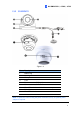
1.3 Overview 1.3.1 GV-EBD2702 / 4700 Figure 1-1 No. Description 1 Bottom ring 2 Housing 3 Lens 4 Infrared indicator 5 Power connector (DC 12 V) 6 Ethernet connector / PoE Note: To power the camera using the power connector (No.5), an optional power adapter is required.
1 GV-EBD2702 / 4700 / 4711 1.3.2 GV-EBD4711 Figure 1-2 No. Description 1 Bottom ring 2 Housing 3 Microphone 4 Lens 5 Power connector (DC 12 V) 6 Ethernet connector / PoE 7 Micro SD card slot and default button compartment 8 Default button 9 Micro SD card slot Note: To power the camera using the power connector (No.5), an optional power adapter is required.
1.4 Installation The Target Eyeball Dome is designed for outdoors. With the standard package, you can install the camera on the ceiling. Or you can purchase optional mounting accessories to mount GV-EBD2702 / 4700 / 4711 on a wall. Below are the instructions for Ceiling Mount. There are two kinds of Ceiling Mount: Concealed Installation and Open Installation. In Concealed Installation, the cables are hidden in the ceiling.
1 GV-EBD2702 / 4700 / 4711 3. Remove the bottom ring by turning it anticlockwise. Bottom Ring Figure 1-5 4. Connect the cables and secure the camera. Figure 1-6 5. Adjust the monitoring direction.
6. Mount the bottom ring. Figure 1-8 For Open Installation Lead the cables out from the open slot on the bottom ring before screwing the camera to the ceiling as shown in step 4 of Conceal Installation.
1 GV-EBD2702 / 4700 / 4711 1.4.2 GV-EBD4711 Installation For Concealed Installation 1. Stick the drill template paster to the ceiling and drill three holes according to the drill template. Figure 1-10 2. Insert the screw anchors. Figure 1-11 3. Loosen the fixing screw and remove the housing by turning it to the position as shown.
4. Secure the bottom ring to the ceiling with 3 supplied screws and connect the cable. Figure 1-13 5. Mount the housing by adjusting to the position as shown and press and turn to anywhere but . Figure 1-14 6. Adjust the monitoring direction. Then tighten the screw.
1 GV-EBD2702 / 4700 / 4711 For Open Installation Lead the cables out from the open slot on the bottom ring before screwing the camera to the ceiling as shown in step 5 of Concealed Installation. Figure 1-16 Note: You can optionally purchase GV-Mount211 or GV-Mount212 for Wall Bracket Mount. For details, see its User’s Manual.
2. GV-ABL2701 The GV-ABL2701 Bullet IP Camera is an outdoor, fixed, network camera equipped with an automatic IR-cut filter and an IR LED for day and night surveillance. The camera supports H.265 video codec to achieve better compression ratio while maintaining high quality image at reduced network bandwidths. The camera adheres to IP66 standards and can be powered through PoE. Model No. GV-ABL2701 2.1 Specifications Fixed lens Description Fixed Iris, f: 4.0 mm, F/1.8, M12 Lens Mount 2 MP, H.
2 2.2 GV-ABL2701 Optional Accessories Optional accessories can expand the capabilities and versatility of your GV-ABL2701. Contact your dealer for more information. Model Number Name Details GV-Mount502 Wall Mount Bracket Dimensions: 93 x 93 x 39 mm (3.66” x 3.66” x 1.53”) Weight: 0.235 kg (0.52 lb) GV-PA191 Power over Ethernet (PoE) GV-PA191 is a Power over Adapter Ethernet (PoE) adapter designed to provide power to the IP device through a single Ethernet cable.
2.3 Overview Figure 2-1 No. Description 1 Power connector (DC 12 V) 2 Ethernet connector / PoE Note: To power the camera using the power connector (No.1), an optional power adapter is required.
2 2.4 GV-ABL2701 Installation The Bullet IP Camera is designed for outdoors. With the standard package, you can install the camera on the wall or ceiling. Or, you can purchase optional mounting accessories to mount your camera on a wall. Below are the instructions for Wall Mount. There are two kinds of Wall Mount: Concealed Installation and Open Installation. In Concealed Installation, the cables are hidden in the wall. In Open Installation, the cables are led out from the open slot on the base.
4. Insert the screw anchors. Figure 2-4 5. Screw the locknut and loosen the universal joint before attaching the camera to the wall. Figure 2-5 6. Secure the camera to the wall and connect all cables.
2 7. GV-ABL2701 Adjust the monitoring direction. Figure 2-7 For Open Installation Lead the cables out from the open slot on the base before screwing the camera to the wall as shown in step 6 in For Concealed Installation. Note: You can optionally purchase GV-Mount502 for Wall Bracket Mount. For details, see its User’s Manual.
3. GV-ADR2701 The GV-ADR2701 Mini Fixed Rugged IP Dome is an outdoor, fixed, network camera equipped with an automatic IR-cut filter and an IR LED for day and night surveillance. The camera supports H.265 video codec to achieve better compression ratio while maintaining high quality image at reduced network bandwidths. The camera adheres to IP66 standards and can be powered through PoE. Model No. GV-ADR2701 3.1 Specifications Fixed lens Description Fixed Iris, f: 2.8 mm, F/2.
3 GV-ADR2701 3.2 Optional Accessories Optional accessories can expand the capabilities and versatility of your GV-ADR2701. Contact your dealer for more information. Model Number Name Details GV-PA191 Power over Ethernet (PoE) GV-PA191 is a Power over Adapter Ethernet (PoE) adapter designed to provide power to the IP device through a single Ethernet cable. GV-PoE Switch GV-PoE Switch is designed to provide power along with network connection for IP devices.
3.3 Overview Figure 3-1 No. Description 1 Ethernet connector / PoE 2 Power connector (DC 12 V) 3 Transparent Dome Cover Note: To power the camera using the power connector (No.2), an optional power adapter is required.
3 GV-ADR2701 3.4 Installation The IR Mini Fixed Rugged IP Dome is designed for outdoors. With the standard package, you can install the camera on the ceiling. Below are the instructions for Ceiling Mount. There are two kinds of Ceiling Mount: Concealed Installation and Open Installation. In Concealed Installation, the cables are hidden in the ceiling. In Open Installation, the cables are led out from the open slot on the camera base. For Concealed Installation 1.
3. Unscrew the transparent dome cover with the supplied torx wrench. 4. Connect the cables and secure the camera. Figure 3-4 5. Adjust the monitoring direction and tighten the screws after vertically adjusting the lens.
3 GV-ADR2701 6. Secure the transparent dome cover with the supplied torx wrench. Figure 3-6 Note: Before securing the transparent dome cover, make sure the waterproof rubber strip is tightly held by the six retainers on the bottom ring. Figure 3-7 For Open Installation Lead the cables out from the open slot on the camera base before screwing the camera to the ceiling as shown in step 4 in For Concealed Installation.
4. Waterproofing the Cable Waterproof the Ethernet cable by using the supplied waterproof rubber set. 1. Attach the seal ring to the RJ-45 plug. Seal ring Figure 4-1 2. Insert the waterproof components through the Ethernet cable as shown below. 3 2 Insert in order Figure 4-2 3. Insert the cylindrical waterproof ring into waterproof bolt.
4 Waterproofing the Cable 4. Insert the cable into the RJ-45 plug and screw the waterproof bolt in. Figure 4-4 5. Screw in the waterproof bolt lid. Bolt lid Figure 4-5 6. Finish the waterproof installation.
5. Accessing the Camera 5.1 System Requirements Once installed, your camera is accessible over the network. Make sure your PC has good network connection and meet the following requirements: CPU Intel Core i5-4670, 3.40 GHz Memory DDR3 8 GB RAM On Board Graphics Intel HD Graphics 4600 (Versions of driver from year 2014 or later required) Web Browsers Internet Explorer 11.0 or above Mozilla Firefox Safari Note: Some functions are not available on non-IE browsers.
5 5.2 Accessing the Camera Looking Up the Dynamic IP Address By default, when the camera is connected to LAN a with DHCP server, it is automatically assigned with a dynamic IP address. Follow the steps below to look up its IP address. Note: The computer you use to configure the IP address must be under the same LAN as your camera. 1. Download and install the GV-IP Device Utility program from http://www.geovision.com.tw/download/product/. 2.
4. The login page appears. Figure 5-3 5. For first-time accessing of the Web interface, download and install the plug-in. 6. Type the default ID and password admin and click Login.
5 5.3 Accessing the Camera Configuring the IP Address If the camera is connected to a LAN without DHCP server, the default IP address will be 192.168.0.10. Follow the steps below to modify the IP address to avoid IP conflict with other GV-IP devices on the same LAN. 1. Open your Web browser, and type the default IP address http://192.168.0.10. 2. Type the default username and password admin. Click Login. 3. Click Setup, select Common in the left menu and select Ethernet. Figure 5-4 4.
6. The Web Interface Once you log in the Web interface, you will see the live view as shown below. Figure 6-1 No. Name Function Set the display ratio of the image. 1 Proportional 2 Live Stream 3 Image 4 Zoom +/- 5 Focus +/- 30 Scale: display images by 16:9. Stretch: display images by window size. Original: display images in its original size. Select a live video stream: main stream, sub stream or third stream (when enabled). Open the image setting page. – See 3.4.
6 The Web Interface 6 Play/Stop Play or stop live video. 7 Volume Only for GV-EBD4711, adjust the audio output volume on the PC. 8 Snapshot Take a snapshot of the current image displayed on the PC. 9 Local Recording Start 10 Digital Zoom 11 Full Screen 12 Control Panel 13 Enable or stop local recording. or disable digital zoom. – See 2.2.1.1 Digital Zoom in the User’s Manual. Display in full screen mode. Only for GV-EBD4711, hide or show the camera’s optical zoom and focus functions.
7. Upgrading System Firmware GeoVision periodically releases updated firmware on the website. To load the new firmware into the camera, follow the instructions below. 1. At the top of the Web interface, click Setup. 2. In the left menu, select System and select Maintenance. This page appears. Figure 7-1 3. Click Browse under Software Upgrade to locate the firmware file (.zip) saved at your local computer. 4. Click Upgrade to process the upgrade.
8 8. Restoring to Factory Default Restoring to Factory Default You can restore the camera to factory default settings using the Web interface or the Default Button. Note: 1. There is no default button on GV-ABL2701 / ADR 2701 / EBD2702 / 4700. 2. For the default button on GV-EBD4711, refer to 1.3.2 GV-EBD4711. 1. In the Web interface, click Setup. 2. In the left menu, select System and select Maintenance. 3. Under the Config Management section, click Default.