Introduction
1
1.1.4 Overview
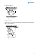
1.1.4.1 GV-EBD2702 / 4700
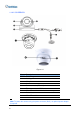
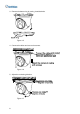
Figure 1-1
No. Description
1 Bottom ring
2 Housing
3 Lens
4 Infrared indicator
5 Power connector (DC 12 V)
6 Ethernet connector / PoE
Note: To power the camera using the power connector (No.5), an optional power adapter
is required.
5