
Installation Manual
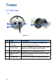
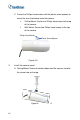
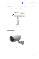
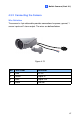

4.2 Overview
Panel
1
2
3
4
5
Figure 4-1
No. Name Description
1
Power & I/O
Connector
Connects to the data cable. For details, see
4.3.2 Connecting the Camera.
Res
ets all configurations to factory default. For
details, see 4.4 Loading Factory Default.
2 Default Button
3 LAN / PoE Cable Connects to a 10/100 Ethernet or PoE.
4
Memory Card
Slot
Receives a micro SD card (SD/SDHC, version
2.0 only, Class 10).
5 Silica gel bag Desiccant that keeps the camera housing dry.
58