Quick Start Guide GV-SNVR3203, GV-SNVR6403 The Vision of Security Thank you for purchasing GV-SNVR. This guide is designed to assist the new user in getting immediate results from the GV-SNVR. For advanced information on how to use the GV-SNVR, please refer to GV-SNVR User's Manual.
© 2022 GeoVision, Inc. All rights reserved. Under the copyright laws, this manual may not be copied, in whole or in part, without the written consent of GeoVision. Every effort has been made to ensure that the information in this manual is accurate. GeoVision, Inc. makes no expressed or implied warranty of any kind and assumes no responsibility for errors or omissions. No liability is assumed for incidental or consequential damages arising from the use of the information or products contained herein.
Content 1 LED INDICATORS……………………………………………………………1 2 OVERVIEW……………………………………………………………………2 2.1 GV-SNVR3203 / GV-SNVR6403 FRONT VIEW .................................. 2 2.2 GV-SNVR3203 / GV-SNVR6403 REAR VIEW ..................................... 3 2.3 FRONT PANEL BUTTONS ....................................................................... 5 3 DISK INSTALLATION ........................................................................... 7 3.1 PREPARATION .......................................................
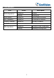
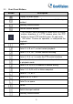
1 LED Indicators LED Status Description Steady on Normal. Blinking Starting up. ALM (Alarm) Steady on Device alarm occurred. NET (Network) Steady on Connected to network. GUARD (Arming) Steady on Arming is enabled. CLOUD Not functional. RUN (Operation) HD (Hard disk) Steady on No disk; or disk is abnormal. Blinking Reading or writing data.
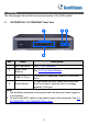
2 Overview The following part shows the front and rear panels of the NVR models. 2.1 GV-SNVR3203 / GV-SNVR6403 Front View 3 1 4 2 No. Name 1 LED Indicators See 1. LED Indicators. 2 Front Panel Buttons See 2.3 Front Panel Buttons. 3 USB 2.0 Ports Connects to a keyboard, mouse, or USB flash drive. Power Button To shut down the NVR, press this button and hold for at least 3 seconds until a message appears. Click yes. 4 Description Note: 1.
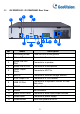
2.2 GV-SNVR3203 / GV-SNVR6403 Rear View 3 6 2 1 7 10 8 4 5 11 12 13 9 No. Name Description 1 Grounding Screw Fixes the NVR to the ground. 2 Network Ports Connects to the network. 3 Audio Line Out Port Connects to a speaker. 4 Audio Line In Port Connects to a microphone. 5 HDMI Output Ports Connects to HD TVs. 6 eSATA Connects to external storage devices. 7 VGA Output Port Connects to a VGA monitor. 8 USB 3.0 Port Connects to a keyboard, mouse, or USB flash drive.
Note: 1. HDMI output ports do not support audio output on the connected monitors. 2. One 4K video output (HDMI) and two 1080p video outputs (HDMI / VGA) are supported. 3. The default IP address is 192.168.0.100 for NIC 1 and 192.168.1.100 for NIC 2. If you want to use the two NICs as WAN and LAN, you must first configure separate IP addresses for the two NICs in different networ segments to avoid IP conflicts (the first two numbers of the address cannot be identical, such as 192.168).
2.3 Front Panel Buttons Button Description Display the main menu. Switch to the next tab on the screen or switch the input method. Auxiliary function button. Exit the current window. The 4 arrows: Switch windows or menu items; or control rotation directions of a PTZ camera when the PTZ toolbar is closed. PTZ stands for pan, tilt, and zoom. OK button: Confirm an operation, or start/pause the playback. Enter 1. Enter 2, A, B, or C; or start instant playback.
Button Description Enter 0 or a space.
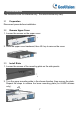
3 Disk Installation The illustrations are for reference only. The actual device may vary. 3.1 Preparation Disconnect power before installation. 3.2 Remove Upper Cover 1. Loosen the screws on the upper cover. 2. Slide the upper cover backward, then lift it up to remove the cover. 3.3 Install Disks 1. Loosen the screws of the mounting plate on the side panels. 2. Turn the upper mounting plate in the shown direction, then remove the plate.
3. Secure the disks on the mounting plate. Fix the screws according to the figure below. Avoid damaging the disk in the process. 4. Put the mounting plate back in place. Connect the power cables and data cables as shown in the figure. Repeat the steps to connect all the disks. 5. Put the cover back in place, and secure it and the mounting plates with screws.
4 Startup and Shutdown Make sure the cables are connected correctly and the device is grounded properly. Use a power supply that meets requirements. 4.1 Startup Connect the device to power and turn on the power switch. 4.2 Shutdown Click > Shutdown on the screen toolbar in live view page. CAUTION! Do not disconnect power when the NVR is operating or shutting down.
5 Local Operations 5.1 Add IP Devices Before you begin, make sure the devices are connected to your NVR via network. 5.1.1 Quick Add Follow the wizard to the fourth step. Select the devices to add in the discovered device list, and then click Add. NOTE! After the device is added, if wrong username or password message shows in the preview window, click in the window toolbar and enter the correct username and password.
5.2 Custom Add 1. Right click in the preview page, click Menu > Camera > Camera. 2. Click Custom Add, enter the IP address and other required information. 3. Check the status of camera. means the camera gets online successfully. If the status icon is grayed out, place your mouse cursor over the icon to view the cause of error. Click the edit button to modify device information. NOTE! • You can also click to add a device. Segment to search for devices in a specified network segment. • Click Search 5.
6 Remote Access via Mobile Devices The NVR supports for remote access via mobile devices based on Android and iOS operating system. Refer to GV-Eye Installation Guide for details on operating instructions. NOTE! This function is only applicable to GV-Eye V3.0.0 or later.
7 Web Login Before you begin, check that your PC is connected to your NVR through network. 1. Open the browser on your PC, enter the IP address (192.168.0.100 / 192.168.1.100) in the address bar, then press Enter. NOTE! Install the plugin as required at first login. Close your browser during the installation. 2. On the login page, enter the default username (admin) and password (123456) or the modified password based on your configurations on the NVR, then click Login.
Safety Warnings Network Security Please take all necessary measures to enhance network security for your device. The following are necessary measures for the network security of your device: ⚫Change default password and set strong password: You are strongly recommended to change the default password after your first login and set a strong password of at least nine characters including all three elements: digits, letters, and special characters.
⚫Check logs: Check your device logs regularly to detect unauthorized access or abnormal operations. ⚫Isolate video surveillance network: Isolating your video surveillance network with other service networks helps prevent unauthorized access to devices in your security system from other service networks. ⚫Physical protection: Keep the device in a locked room or cabinet to prevent unauthorized physical access. ⚫SNMP: Disable SNMP if you do not use it. If you do use it, then SNMPv3 is recommended.
⚫Use a mains socket outlet with a protective earthing (grounding) connection. ⚫Ground your device properly if the device is intended to be grounded. Battery Use Caution ⚫When battery is used, avoid: ➢ Extremely high or low temperature and air pressure during use, storage, and transportation. ➢ Battery replacement. ⚫Use the battery properly. Improper use of the battery such as the following may cause risks of fire, explosion or leakage of flammable liquid or gas.