
Manual

Signet 2100 Turbine Sensor Operating Instructions
WARNING!
1. Do not remove from pressurized lines.
2. Never install sensor without O-rings.
3. Confi rm chemical compatibility before use.
4. Do not exceed maximum temperature/pressure specifi cations.
5. Wear safety goggles and faceshield during installation/service.
6. Failure to follow safety instructions could result in severe personal injury.
Contents
1. Installation/Mounting
2. Sensor Wiring
3. Calibration
4. Specifi cations
5. Parts and Accessories
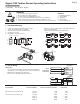
1. Installation/Mounting
1. Install sensor with arrow pointing in the direction
of fl ow. All mounting angles acceptable.
2. Slide union nut onto pipe or fl exible tubing.
3. Install end connectors.
4. Hand tighten union nut to secure.
• Suitable for clear or opaque fl uids. Suspended solids may
cause mechanical failure.
• Upstream/downstream mounting requirements:
10x I.D.
5x I.D.
Inlet Outlet
Flange
15x I.D.
5x I.D.
Reducer
40x I.D.
5x I.D.
2 x 90° Elbow
50x I.D.
Valve/Gate
5x I.D.
20x I.D.
5x I.D.
90° Elbow
25x I.D.
5x I.D.
2 x 90° Elbow
64 mm
(2.5 in.)
33.3 mm
(1.3 in.)
43.2 mm
(1.5 in.)
12.2 mm
(.48 in.)
Pipe
End Connector
Union Nut
Reversible
electronics
O-rings
(factory installed)
Press to release
2. Sensor Wiring
Wiring Tips:
• Use 2-conductor twisted-pair shielded cable (Belden #8451 or
equivalent) for sensor cable splices up to 300 m (1000 ft) max.
• Maintain cable shield through cable splice.
• Route sensor cable away from AC power lines.
Black (5 to 24 VDC)
Red (Signal out)
Shield (DC return)
Blk
Power
Red
Freq. input
Shld
Gnd
Signet
2100 Turbine
Flow Sensor
Signet
Instrument
Input
Gnd.
10 kΩ
+
5 to 24
VDC
-
Black
Shield
Red
Other
instrument
Other
Instrument
*3-2100.090-1*
3-2100.090-1 Rev. G 02/10 English
English
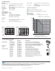
3. Calibration
Sensor Model Connection Option K-Factors: Pulses/U.S. Gallon Pulses/Liter
High Flow Sensors 3-2100-1H, 2H 1/2" Pipe 1725 456
1/2" Hose 1700 449
Low Flow Sensors 3-2100-1L, 2L 1/2" Pipe 12250 3236
1/4" Hose 12800 3382
3/8" Hose 13000 3435
1/2" Hose 12500 3303