
Manual


2
2350 Temperature Sensor
3. Installation
The compact integral assembly can be installed using the
following directions:
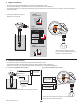
3.2 2350-3 In-line Remote Assembly
The optional 3-8052-1 Integral Junction box with ¾ in. process
connection offers a convenient terminal point to extend the 2350
cable over distances greater than 4.6 m (15 ft).
• The kit includes:
• ¾ in. NPT process connection
• Conduit base and cap with junction terminals
• 3-9000.392-1 liquid tight connector, ½ in. NPT
To extend the wires longer than 4.6 m (15 ft):
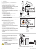
• Modify sensor 3-2350-1 or 3-2350-3 as described in fi gure 1.
• Terminate the three wires to the terminal board located in the
cap assembly.
• Add customer-supplied wire to extend the cable.
• Terminate to the transmitter or the 4 to 20 mA input device.
• Apply sealant or PTFE tape to the process connection threads
per fi gure 3, after inspecting threads to ensure integrity.
DO NOT install a sensor with damaged threads.
• Tighten the sensor 1½ turns past fi nger tight into the process
connection.
3.1 2350-1 Integral Assembly Sensor Modifi cation
• Modify sensor part number 3-2350-1 per fi gure 1.
• Apply sealant or PTFE tape to the process connection threads
per fi gure 2, after inspecting threads to ensure integrity. Do not
install a sensor with damaged threads.
• Thread the sensor into the 3-8052 mounting kit.
• Tighten the sensor 1½ turns past fi nger tight into the process
connection.
• Make sure the fl ow alignment indicator is in correct position in
the pipe. Damage to the sensor tip can occur if the sensor tip is
installed improperly.
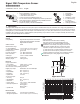
• Install 8350 transmitter
or 9900
(refer to 8350 or 9900 manual for wiring information).
• The 3-8052 Integral kit includes:
•
3
/
4
in. NPT process connection
• 3-9000.392-1 liquid tight connector,
1
/
2
in. NPT
• Conduit base to attach 8350.
3.3 2350-1 or 2350-3 Submersible Installation
• Use the 2350-1 or 2350-3 sensor with 4.6 m (15 ft) cable.
• Mount the sensor to an extension pipe or watertight conduit
using thread sealant.
• Use a cable gland at the top of the extension to prevent
moisture intrusion/accumulation inside the pipe.
• For additional defense against possible accumulation of
condensation at the back seal area of the sensor, fi ll the lower
75 mm to 100 mm (3 in. to 4 in.) of conduit or extension pipe
with a fl exible sealant such as silicone.
4-20
mA
FREQ/
DATA
WHT WHT
BLU BLK
N/C RED
SHIELD
SENSOR
INPUT
*
SHIELD
–
+
FREQ/
DATA
3-8052-1
Integral junction box,
3/4 in. NPT
*Customer supplied extension cable
must not exceed 305 m (1000 ft.)
*
3-8052
Integral mount kit
3-9900
3-8350
3-9900.396
Angle Adjustment Adapter Kit
*Customer supplied extension cable
must not exceed 305 m (1000 ft.)
152 mm
(6 in.)
Figure 1
Figure 2
Figure 3
Fill with
3 to 4 in.
of sealant
MXQFWLRQER[UHFRPPHQGHG
Align with
flow stream
Flow
NOTE:
The 8050-1 or the 8052-1 junction boxes can be useful
accessories for this installation option.
CAUTION!
The fl uid temperature must not exceed 85 °C (185 °F)
in submersible installations.