
Manual


2540 High Performance Flow Sensor
3
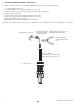
process pipe
sensor fitting
bleed valve
make sure
bleed valve
clears isolation
valve handle
5. Installation
The following items are required to properly install Signet 2540 Sensors.
5.1 Hardware, Standard Sensor
• Female pipe fi tting (weld-on or saddle) with 1½ in. NPT or ISO 7-Rc 1½ threads
• 32 mm (1¼ in.) diameter drill
• Pipe thread sealant
• Tape measure
5.2 Hardware, Hot-Tap Sensor
The Hot-Tap sensor requires all the standard sensor items plus:
• Hot-Tap drilling machine (e.g., Mueller drilling machine or equivalent)
• Female ball or gate valve (full port only) with 1½ in. NPT or ISO 7-Rc 1½ threads
• Male pipe nipple, 32 x 50 mm (1½ x 2 in.) with 1½ in. NPT or ISO 7-R 1½ threads
• Hot-Tap installation tool (purchased separately)
5.3 Standard Fitting Installation
A. Depressurize and drain pipe.
B. Wearing safety face protection, drill a 32 mm (1¼ in.) diameter hole in the
pipe.
C. Install the pipe fi tting of the outside of the pipe according to the manufacturer's
instructions. Failure to follow these instructions may result in serious bodily
injury and/or product failure.
D. Remove sensor fi tting from sensor assembly.
E. Thread sensor fi tting into pipe fi tting. (Fig. 1)
5.4 Hot-Tap Fitting Installation
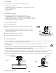
A. Install the pipe fi tting on the outside diameter of the pipe according to the manufacturer's instructions. Failure to follow these
instructions may result in serious bodily injury and/or product failure.
B. Install the pipe nipple and isolation valve (ball or gate valve) onto the external pipe fi tting using pipe sealant on the
threads. (Fig. 2)
C. Wearing safety face protection, install an appropriate hole cutting tool per manufacturer's instructions (e.g., Mueller
drilling machine) with a 32 mm (1.25 in.) drill onto the top of the isolation valve, ensuring a tight fi t. Use the
recommended drill bit size or damage to the isolation valve may occur.
D. Open the isolation valve and insert the drill through the valve and cut the sensor clearance hole. After the hole is cut, withdraw the
drill from the isolation valve and close the valve. Remove the drilling machine per manufacturer's instructions. (Fig. 3)
E. Install the sensor fi tting/bleed valve into the top of the isolation valve. Make sure the bleed valve clears the handle of the isolation
valve during operation.
pipe
fitting
process
pipe
pipe sealant recommended
sensor
fitting
customer supplied
nipple: 32 x 50 mm
(1.25 x 2 in.) long
customer supplied
ball or gate valve
process pipe (side view)
Fig. 2
Fig. 3
Fig. 1