
Manual


2540 High Performance Flow Sensor
4
"H"
alignment rod
sensor flange
process pipe
direction
of flow
pipe side view
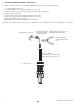
5.5 Calculating the H Dimension
Before installing the sensor some critical dimensions must be established (for Hot-Tap installations,
we assume the pipe dimensions are known). The rotor shaft must be located 10% inside the pipe I.D.
to ensure accurate calibration capability. To accomplish this, the "H" dimension is measured from the
outside surface of the pipe to the bottom of the sensor fl ange.
Nominal "H" dimensions for standard pipes are listed here. For non-standard pipe dimensions, calculate
the "H" dimension using the formula listed below. The wall thickness and inside diameter (I.D.) are
required for the "H" dimension calculation.
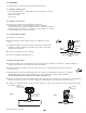
The 6 inch ruler (included) may be used to measure your pipe I.D. and wall thickness up to 5 inches
(standard sensors only).
Pipe wall thickness: __________ Pipe I.D.: ___________
A
B
1
2
3
4
5
6
1
2
3
4
5
A
B
1
2
3
4
5
6
1
2
3
4
5
pipe I.D.
wall
thickness
A
B
1
2
3
4
5
6
1
2
3
4
5
incorrect
correct
H Dimensions, Standard Sensors (2540-1, 2540-2)
Wrought Steel Pipe Per ANSI 36.10
NPS SCH 40 SCH 80 STD XS
inches inches inches inches inches
1½ 4.924 4.880 4.924 4.880
2 4.869 4.818 4.869 4.818
2½ 4.780 4.722 4.780 4.722
3 4.707 4.640 4.707 4.640
3½ 4.649 4.576 4.649 4.576
4 4.590 4.510 4.590 4.510
5 4.467 4.374 4.467 4.374
6 4.344 4.222 4.344 4.222
8 4.110 3.968 4.110 3.968
10 3.863 3.680 3.863 3.755
12 3.630 3.405 3.655 3.555
14 3.480 3.230 3.530 3.430
16 3.230 2.955 3.330 3.230
18 2.980 2.680 3.130 3.030
20 2.755 2.405 2.930 2.830
22 ----- 2.130 2.730 2.630
24 2.280 1.855 2.530 2.430
Stainless Steel Pipe Per ANSI B36.19
NPS SCH 5S SCH 10S SCH 40S SCH 80S
inches inches inches inches inches
1½ 4.988 4.953 4.924 4.880
2 4.940 4.905 4.869 4.818
2½ 4.876 4.847 4.780 4.722
3 4.814 4.784 4.707 4.640
3½ 4.764 4.734 4.649 4.576
4 4.714 4.684 4.590 4.510
5 4.586 4.567 4.467 4.374
6 4.480 4.460 4.344 4.222
8 4.280 4.249 4.110 3.968
10 4.048 4.023 3.863 3.755
12 3.830 3.811 3.655 3.555
14 3.705 3.680 ----- -----
16 3.498 3.480 ----- -----
18 3.298 3.280 ----- -----
20 3.080 3.056 ----- -----
22 2.880 2.856 ----- -----
24 2.656 2.630 ----- -----
Wrought Steel Pipe Per ANSI 36.10
NPS SCH 40 SCH 80 STD XS
inches inches inches inches inches
1 ½ 15.084 15.040 15.084 15.040
2 15.029 14.978 15.029 14.978
2 ½ 14.940 14.882 14.940 14.882
3 14.867 14.800 14.867 14.800
3½ 14.809 14.736 14.809 14.736
4 14.750 14.670 14.750 14.670
5 14.627 14.534 14.627 14.534
6 14.534 14.382 14.534 14.382
8 14.270 14.128 14.270 14.128
10 14.023 13.840 14.023 13.915
12 13.790 13.565 13.815 13.715
14 13.640 13.390 13.690 13.590
16 13.390 13.115 13.490 13.390
18 13.140 12.840 13.290 13.190
20 12.915 12.565 13.090 12.990
22 ----- 12.290 12.890 12.790
24 12.440 12.015 12.690 12.590
Stainless Steel Pipe Per ANSI B36.19
NPS SCH 5S SCH 10S SCH 40S SCH 80S
inches inches inches inches inches
1 ½ 15.148 15.113 15.084 15.040
2 15.101 15.065 15.029 14.978
2 ½ 15.036 15.007 14.940 14.882
3 14.974 14.944 14.867 14.800
3 ½ 14.924 14.894 14.809 14.736
4 14.874 14.844 14.750 14.670
5 14.747 14.727 14.627 14.534
6 14.640 14.620 14.534 14.382
8 14.440 14.409 14.270 14.128
10 14.208 14.183 14.023 13.915
12 13.990 13.971 13.815 13.715
14 13.865 13.840 ----- -----
16 13.658 13.640 ----- -----
18 13.458 13.440 ----- -----
20 13.240 13.216 ----- -----
22 13.040 13.016 ----- -----
24 12.816 12.790 ----- -----
(-----) unavailable
(-----) unavailable
Standard Sensors: H = 5.23 - wall thickness - (0.10 x I.D.)
Hot-Tap Sensors: H=15.39 in. - wall thickness - (0.10 x I.D.)
Example: 3.0 inch schedule 80 wrought steel
Wall thickness = 0.3 in. / Inside diameter = 2.9 in.
H = 5.23 - 0.3 - (0.10 X 2.9) / H = 117.86 mm (4.64 in.)
Record your sensor's "H" dimension for future reference: H= ___________
After correct dimensions are calculated and recorded, the sensor can be installed in the
fi tting. The Standard and Hot-Tap versions require substantially different procedures.
H Dimensions, Hot-Tap Sensors (2540-3, 2540-4)