
User guide

6 2551 Magmeter
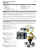
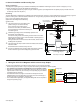
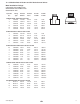
• When the blue jumper illustrated here is placed over both pins, the
2551-XX-11 outputs an open collector frequency signal that can be
connected to any powered Signet ow meter (models 5600, 8900,
9900).
• 5 VDC power is provided to the 2551 Magmeter by all Signet ow
instruments. No additional power is required.
• The frequency output will be displayed as positive ow
regardless of the ow direction.
• When the blue jumper illustrated here is removed (or placed over
one pin for storage) the 2551-XX-11 outputs a Digital (S
3
L) signal
compatible with the Signet 8900 and 9900.
• The 2551 receives 5 VDC power from the 8900 or 9900. No
additional power is required.
• The 8900 will display 0 (Zero) ow rate during periods of
reverse ow. The 9900 will display negative numbers to
indicate reverse ow.
• The maximum cable length from the 2551 to the 8900 or 9900
depends on the 8900 or 9900 con guration. Refer to the 8900 or
9900 manual for complete information.
Blue Jumper OFF = S
3
L OUT
S L
3
3
4
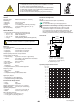
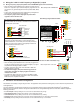
8. Wiring the 3-2551-11 with Frequency or Digital (S
3
L) output
1
2
3
4
10K
5-24 VDC
Ground
Not used
Frequency Out
2551 Magmeter
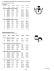
Install a pull-up resistor when connecting the
2551 Magmeter to other manufacturer's flowmeters.
2551 Frequency Out to other manufacturer's equipment
Blue Jumper ON = FREQ OUT
3
4
Frequency
1
2
3
4
5-24 VDC
Ground
Not used
Sensr Gnd
(SHIELD)
Sensr IN
(RED)
Sensr V+
(BLACK)
2551 Magmeter
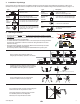
Flow Transmitter
Frequency
AUX power MUST be connected on the 5600 Flow Transmitter
to provide power to the 2551.
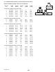
3-8900.621C
I/O Module 3-8900.401-X
1
2
3
4
5
6
7
8
9
10
11
+5VDC (Black)
Freq. Input (Red)
GND (Shield)
+5VDC (Black)
Freq. Input 2 (Red)
S L (Red)
GND (White/Shield)
+5VDC (Black)
S L (Red)
GND (White/Shield)
3
3
Frequency
Input
1
Frequency
Input 2
OR
S
3
L
Input
2
S
3
L
Input
1
1
2
3
4
Freq.
S
3
L
Ground
+5 VDC
Not used
Data
2551 Magmeter
2551 Wiring to Signet 8900 and 9900
2551 Frequency Out to Signet 5600
9. Calibration and Software Con guration
No calibration is necessary to begin using the 2551. The application and performance settings are pre-set to meet the requirements of
most applications.
The 2551 application and performance settings can be customized using the Signet 3-0250 USB to Digital (S
3
L) Con guration/
Diagnostic Tool and software. Refer to the Signet 3-0250 USB-to-S
3
L Con guration/Diagnostic Tool manual for details to adjust the
following parameters:
• 4 to 20 mA span: Factory setting is 0 to 5 m/s. Can be customized to any range.
• Noise Rejection Filter: Factory set for 60 Hz. Can be changed to 50 Hz.
• Low Flow Cutoff: Factory setting is 0.05 m/s. Can be customized to any velocity.
• Averaging Time: Factory setting is 14 seconds. Can be customized from 0.1 seconds to 100 seconds.
• Sensitivity: Factory setting is 25% of full scale. Can be customized to any % of full scale.
If connecting the 2551 Magmeter to a ow instrument from
another manufacturer, 5 to 24 VDC power must be provided to
the 2551. A 10 K pull-up resistor (not supplied) must also be
connected between terminals 1 and 2.
8.1 Wiring: Frequency output (Compatible with all POWERED Signet Flow instruments.)
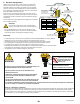
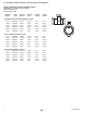
8.2 Wiring: S
3
L output (Compatible with 8900 Multi-Parameter Controller and 9900 Transmitter only)
DATA
GND
SHLD
V+
1
2
3
4
2551 Magmeter
9900 Transmitter
+5 VDC
Ground
Not used
Frequency or S
3
L