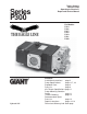
Series P300 Triplex Ceramic Plunger Pump Operating Instructions/ Repair and Service Manual For Models: P314 P316 P317 P318 P319 P321 P340 Updated 5/07 Contents: Installation Instructions: page 2 Pump Specifications: pages 3-7, 10 Exploded View: page 8 Parts List: page 9 Kits/Torque Specifications: page 11 Pump Mounting Selection Guide: page 11 Trouble Shooting: page 12 Recommended Spare Parts List: page 12 Repair Instructions: pages 13-14 Dimensions/Warranty Info: back page
INSTALLATION INSTRUCTIONS 4. Use of a dampener is necessary to minimize pulsation at drive elements, plumbing, connections, and other system areas. The use of a dampener with Giant Industries, Inc. pumps is optional, although recommended by Giant Industries, Inc. to further reduce system pulsation. Dampeners can also reduce the severity of pressure spikes that occur in systems using a shut-off gun. A dampener must be positioned downstream from the unloader. Installation of the Giant Industries, Inc.
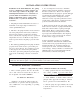
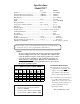
Specifications Model P314/P321 U.S. (Metric) Volume .......................................................... Up to 4.1 GPM ....... (15.5 LPM) Discharge Pressure P321 (Continuous) ...... Up to 3200 PSI ....... (220 bar) Discharge Pressure P321 (Intermittent) ...... Up to 3500 PSI ............. (240 bar) Discharge Pressure P314 (Continuous) .......... Up to 3500 PSI ......... (240 bar) Discharge Pressure P314 (Intermittent) .......... Up to 4000 PSI ......... (275 bar) Inlet Pressure .......................
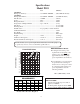
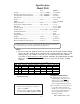
Specifications Model P316 U.S. (Metric) 1450 RPM Ratings (Continuous) .................................... 4.4 GPM @ 3000 PSI ..... (16.7 LPM @ 200 bar) Ratings (Intermittent) .................................... 4.4 GPM @ 3500 PSI ..... (16.7 LPM @ 240 bar) 1750 RPM Ratings (Continuous) .................................... 5.3 GPM @ 2500 PSI ..... (20.0 LPM @ 175 bar) Ratings (Intermittent) .................................... 5.3 GPM @ 3000 PSI ..... (20.0 LPM @ 200 bar) Inlet Pressure ...................
Specifications Model P317 U.S. (Metric) Volume ............................................................ 3.7 GPM ................... (14.0 LPM) Discharge Pressure (Continuous) ................... 3000 PSI ................... (200 bar) Discharge Pressure (Intermittent) ................... 3500 PSI ................... (240 bar) Inlet Pressure ..................................................................................... Up to 90 PSI Stroke ............................................................
Specifications Model P318 U.S. (Metric) 1450 RPM Ratings (Continuous) ...................................... 5.5 GPM @ 2000 PSI ...... (20.8 LPM @ 140 bar) 1750 RPM Ratings (Intermittent) ..................................... 6.6 GPM @ 1000 PSI ...... (25 LPM @ 70 bar) Inlet Pressure .................................................. 140 PSI ............................. (10 bar) Stroke .............................................................. 0.63” .................................
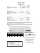
Specifications Model P319 U.S. (Metric) Volume .......................................................... Up to 4.8 GPM ....... (18.2 LPM) Discharge Pressure (Continuous) ................ Up to 2500 PSI ....... (175 bar) Discharge Pressure (Intermittent) ................ Up to 3000 PSI ....... (200 bar) Inlet Pressure ................................................. Positive Inlet Pressure Required Stroke ............................................................. 0.31” ........................ 8mm RPM .
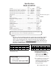
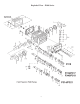
Exploded View - P300 Series 8
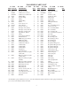
P300 SERIES PARTS LIST A = P321 ITEM 1 2 3 3 3A 3B 4 5 5A 6 6A 6B 7 7 8 8 9 10 11 12 12 12A 13 13 13 13 14 15 16 PART NO. 08326 06773 08410B 08410-LG 07190 13262 08328 06273 08192 07188 01176-2 01196 08303 08303 08330 08491 07193 07225 08331 01086 01086 07760 06712 08478 08340 06508 06207 08333 08413 16 08453 16 08452 16 16A 16B 16B 16B 16C 16C 16D 16D 17 06540 08367 08455 08449 06541 08456 08450 07676 08451 06542 B = P314 C = P316 D = P317 DESCRIPTION QTY.
Specifications Model P340 U.S. (Metric) Volume ............................................................ Up to 3.5 GPM ......... (13.2 LPM) Discharge Pressure (Continuous) ................... Up to 3500 PSI ......... (240 bar) Discharge Pressure (Intermittent) ................... Up to 4000 PSI ......... (275 bar) Inlet Pressure ..................................................................................... Up to 90 PSI Stroke .............................................................. 0.55” ...
P300 SERIES REPAIR KITS Plunger Packing Kits Oil Seal Kit - # 09144 P314/P321 - # 09152 Item 23 23A 24 Part # 07391 08598 07392 Description Grooved Seal Ring Grooved Seal Pressure Ring, 12mm Item 19 Qty. 3 3 3 Part # 08477 08087 07904 P316/P317/P319 - # 09456 Description Gooved Seal, Black Grooved Seal, Brown Pressure Ring, 18mm Qty. 3 3 6 Description Grooved Seal, 20mm Pressure Ring, 20mm Qty.
PUMP SYSTEM MALFUNCTION PUMP SYSTEM MALFUNCTIONS MALFUNCTION CAUSE REMEDY The Pressure and/ or the Delivery Drops Worn packing seals Replace packing seals Broken valve springs Belt slippage Worn or Damaged nozzle Fouled discharge valve Worn or Plugged relief valve on pump Unloader Replace springs Tighten or Replace belt Replace nozzle Clean valve assembly Clean, Reset, and Replace worn parts Check suction lines on inlet of pump for restrictions Check for proper operation Water in Crankcase High Hu
REPAIR INSTRUCTIONS - P300 SERIES NOTE: Always take time to lubricate all metal and nonmetal parts with a light film of oil before reassembly. This step will ensure proper fit, at the same time protecting the pump nonmetal parts (i.e., the elastomers) from cutting and scoring. 1. With a 24mm socket wrench, remove the (3) discharge valve plugs and (3) inlet valve plugs (#32). Inspect the o-ring (#33) for wear and replace if damaged. 2.
REPAIR INSTRUCTIONS - P300 SERIES 9. Remove the pressure rings (#24) and grooved seals (#23) from the valve casing (#26). Inspect parts for wear and replace if necessary. For P318 only, the spacers (#23A) can now be removed. 12. For all pumps (except P318), use a flat screw driver to pry the oil seals (#19) loose from the seal case (#20) . For P318 Pumps Note: Occasionally, this procedure can be carried out for P318 pumps.
REPAIR INSTRUCTIONS - P300 SERIES Reassembly sequence of the P300 Series pump 14. If the oil seals (#19) were removed, replace them with the primary seal lip (grooved side) towards the crankcase and the dust lip (tapered end) towards the valve casing (#26). Lubricate the seal before replacing. Install the oil scraper (#18) over the plunger. each seal case (#20). 17. For P318 only, place the spacer (#23A) (#23B) into the valve casing (#26).
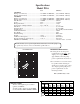
P300 SERIES DIMENSIONS - INCHES (mm) GIANT INDUSTRIES LIMITED WARRANTY Giant Industries, Inc. pumps and accessories are warranted by the manufacturer to be free from defects in workmanship and material as follows: 1. For portable pressure washers and self-serve car wash applications, the discharge manifolds will never fail, period. If they ever fail, we will replace them free of charge.