Triplex Ceramic Plunger Pump Operating Instructions/ Manual Models GP5136-5100 & GP5145-5100 Contents: Installation Instructions: Pump Specifications: Kits/Torque Specs: Recommended Maintenance: Exploded View/Parts List: Trouble Shooting: Repair Instructions: Dimensions: Warranty Information page 2 pages 3-4 page 5 page 5 pages 6-7 page 8 pages 9-10 page 11 back page
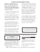
INSTALLATION INSTRUCTIONS Installation of the Giant Industries, Inc., pump is not a complicated procedure, but there are some basic steps common to all pumps. The following information is to be considered as a general outline for installation. If you have unique requirements, please contact Giant Industries, Inc. or your local distributor for assistance. Industries, Inc. to further reduce system pulsation. Dampeners can also reduce the severity of pressure spikes that occur in systems using a shut-off gun.
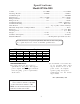
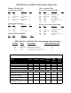
Specifications Model GP5136-5100 Volume ............................................................................... 33.8 GPM ...................................... 127.8 LPM Discharge Pressure .............................................................. 2320 PSI ............................................ 160 Bar Crankshaft Speed .......................................................................................................................... 910 RPM Inlet Pressure ...........................
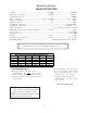
Specifications Model GP5145-5100 Volume .................................................................................. 43.5 GPM ..........................................164.6 LPM Discharge Pressure ........................................................ 1450 PSI ............................................ 100 Bar Crankshaft Speed ......................................................................................................................... 750 RPM Inlet Pressure ............................
GP5136-5100 and GP5145-5100 Pumps Repair Kits Valve Assembly Kits Plunger Packing Kits GP5136-5100 (p/n 09597) Item 35A 35B 36 37A 39 40 Part # 07303 13286 13291-0020 07910 07142-0100 07144 Inlet Valve Kit (p/n 09231-0100) Description O-Ring O-Ring Grooved Ring O-Ring Pressure Ring V-Sleeve Qty. 6 3 3 6 3 6 Item 46A 46C 46D 46E 46F 46G 48B Part # 12055 13304-0100 13306-0100 13307 13308 13309 07740 Description Qty. O-Ring 1 Inlet Valve Assy.
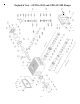
55 Exploded View - GP5136-5100 and GP5145-5100 Pumps 6
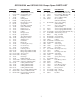
GP5136-5100 and GP5145-5100 Pumps Spare PARTS LIST ITEMPART 1 13266 2 13000 3 07841-0100 4 13267 5 13268 8 07105 9 01009 10 07008 11 06725 12 07703 13 13269 14 13271 15 13272 16 08182 17 13358 18 06725 20 13206 20A 13207 21 13273 22 13274 23 13275 24 13276 25 13280 28 13281 29A 07125 29B 07130 29B 13283 29C 07131-0100 29D 07161-0100 30 13282 31 13284 35 13288-0100 35 13287-0100 35A 07303 35A 13286 35B 13286 35B 08183 36 13291-0020 37 06574-0100 37 06145-0100 DESCRIPTION QTY.
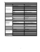
PUMP SYSTEM TROUBLESHOOTING CHART MALFUNCTION The Pressure and/ or the delivery Drops CAUSE REMEDY Worn packing seals Broken valve springs Belt slippage Worn or Damaged nozzle Fouled discharge valve Worn or plugged relief valve on pump Unloader Replace packing seals Replace springs Tighten or replace belt Replace nozzle Clean valve assembly Clean, Reset, and Replace worn parts Check inlet lines of pump for restrictions or leakage Check for proper operation High Humidity Worn Seals Reduce oil change
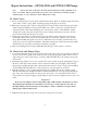
Repair Instructions - GP5136-5100 and GP5145-5100 Pumps Note: Always take time to lubricate all metal and nonmetal parts with a light film of oil before reassembly. This step will ensure proper fit, at the same time protecting the pump's nonmetal parts (i.e., the elastomers) from cutting and scoring. To Check Valves 1. Screw-out inner hexagon screws (48A) with an allen wrench. Remove discharge plugs (48) with a screw driver. Check o-rings (48B) on discharge plugs and replace as necessary. 2.
Repair Instructions - GP5136-5100 and GP5145-5100 Pumps To Disassemble Gear End 1. Loosen inner hexagon screws (49) for the valve casing (43) with an allen wrench. Carefully remove valve casing from the crankcase (1). 2. Drain oil from the crankcase (1) by removing drain plug (12) with a 3/4" wrench. 3. Loosen inner hexagon screws (10) for the crankcase cover (4) with an allen wrench and remove crankcase cover. 4. Loosen hexagon screws (17) for the bearing covers (14) with a wrench and remove bearing cover.
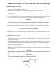
Pump Dimensions - GP5136-5100 and GP5145-5100 Pumps - Inches (mm) 11
GIANT INDUSTRIES LIMITED WARRANTY Giant Industries, Inc. pumps and accessories are warranted by the manufacturer to be free from defects in workmanship and material as follows: 1. For portable pressure washers and car wash applications, the discharge manifolds will never fail, period. If they ever fail, we will replace them free of charge.