Triplex Ceramic Plunger Pump Models Manual Models GP8055, GP8060, GP8065 Updated 3/07 Contents: Installation Instructions: Pump Specifications: Exploded View/Parts List: Repair Kits/Tool List:/Torque Specifications Troubleshooting Chart: Repair Instructions: Dimensions: Warranty Information page 2 page 3-5 pages 6-7 page 8 page 8 pages 9-11 back page back page
INSTALLATION INSTRUCTIONS Installation of the Giant Industries, Inc., pump is not a complicated procedure, but there are some basic steps common to all pumps. The following information is to be considered as a general outline for installation. If you have unique requirements, please contact Giant Industries, Inc. or your local distributor for assistance. 5. Crankshaft rotation on Giant Industries, Inc. pumps should be made in the direction designated by the arrows on the pump crankcase.
Specifications Model GP8055 U.S. (Metric) Volume ............................................................. Up to 75.5 GPM ...... (285 LPM) Discharge Pressure .......................................... Up to 3000 PSI ........ (200 bar) Speed ............................................................... Up to 580 RPM ....... 580 RPM Inlet Pressure ................................................... Up to 29 PSI ............ (2.0 bar) Plunger Diameter ............................................. 2.17” .
Specifications Model GP8060 U.S. (Metric) Volume ............................................................. Up to 90 GPM ......... (341 LPM) Discharge Pressure .......................................... Up to 2500 PSI ........ (172 bar) Speed ............................................................... Up to 580 RPM ....... 580 RPM Inlet Pressure ................................................... Up to 29 PSI ............ (2.0 bar) Plunger Diameter ............................................. 2.
Specifications Model GP8065 U.S. (Metric) Volume ............................................................ Up to 105 GPM ........ (400 LPM) Discharge Pressure ......................................... Up to 2000 PSI ......... (140 bar) Speed .............................................................. Up to 580 RPM ........ 580 RPM Inlet Pressure .................................................. Up to 29 PSI ............ (2.0 bar) Plunger Diameter ............................................ 2.55” ...
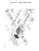
Exploded View - GP8050, GP8060, GP8065 6
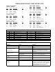
Part List - GP8050, GP8060, GP8065 Item 1 2 8 9 12 13 14 14A 15 16 17 18 19 20 21 21A 21B 21C 22 22 22A 23 24 25 28 29 30 30A 30B 30C 30D 31 32 32A 33 33A 33B 33C 34 36A Part 05024 06912 05035 06225 07109 07182 05036 05111 05112 05037 05038 05039 05040 05041 05044 05042 05043 05113 05045 05114 05046 05104 05047 05048 05049 05057 05052 07225-0100 13136 05053 05050 07623 05058 05057 05055 05056 05054 05059 05060 05063 36B 36B 36B 36C 36D 36E 38 38 38A 38A 38B 39 39 39 39A 40 40 40 05115 05061 05280 05062 0
GP8055/GP8060/GP8065 PUMP REPAIR KITS Plunger Packing Kits GP8055 - #09616 Item 38A 38B 39A 40 42 Part # 13286 05281 05066 07723 05277 Description O-Ring Support Ring O-Ring Seal Ring V-Sleeve Oil Seal Kit - #09221 Item 33A 33B 33C Qty. 6 6 6 3 9 Part # 06667 05066 05067 05069 Description O-Ring O-Ring Seal Ring V-Sleeve Item 53B 53C 53D 53E 53F Qty.
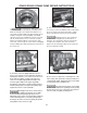
GP8055/GP8060/GP8065 PUMP REPAIR INSTRUCTIONS Valve Inspection and Repair 1) Remove bolts (58). 2) Remove discharge casing (50B) up and away. 3) Take out pressure springs (57A). Pull out assembled valves (51 & 52) with fitting tool. 4) The spring tension cap (51A, 52A) is screwed together with the valve seat (51B or 52B). Screw off spring tension cap. Takeout springs (51E, 52E) and valve plate (51C, 52C). Check sealing surfaces and O-rings (51D, 52D). Replace worn parts.
GP8055/GP8060/GP8065 PUMP REPAIR INSTRUCTIONS 7) Be careful not to damage the seal sleeve (39) and pressure ring (41). Check the inner diameter of the pressure ring for wear and if necessary replace together with seals (40) and (42). Clean all parts. New parts should be lightly coated with silicon grease before installation. Inert the seal unit (40, 41, 42 43) into the sleeve. Push the ceramic plunger carefully through the seals from the crankcase side.
GP8055/GP8060/GP8065 PUMP REPAIR INSTRUCTIONS To Dismantle Crankcase Gear 10) Take out plungers and seal sleeves as described above. Drain the oil by taking off the plug (12). After removing the clip ring (33B), lever out the seal retainer (33) with a screwdriver. Open hose adaptor (K11) and remove gear cover (K3). Remove the cooling vane plate (K1) by removing the screws (K4) 11) Remove the connecting rod screws (24).
GP8050, GP8060, GP8065 SERIES DIMENSIONS - (mm) GIANT INDUSTRIES LIMITED WARRANTY Giant Industries, Inc. pumps and accessories are warranted by the manufacturer to be free from defects in workmanship and material as follows: 1. For portable pressure washers and self-service car wash applications, the discharge manifolds will never fail, period. If they ever fail, we will replace them free of charge.