Model LP301A-5100 Triplex Ceramic Plunger Pump Operating Instructions/ Manual Contents: Installation Instructions: Specifications: Exploded View: Parts List / Kits: Repair Instructions: Pump Mounting Selection Guide: Torque Specifications: Trouble Shooting/Preventative Maintenance Check-List & Recommended Spare Parts List: Dimensions: Warranty Information: page 2 page 3 page 4 page 5 page 6-9 page 9 page 9 page 10 page 11 back page
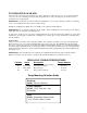
INSTALLATION INSTRUCTIONS Installation of the Giant Industries, Inc., pump is not a complicated procedure, but there are some basic steps common to all pumps. The following information is to be considered as a general outline for installation. If you have unique requirements, please contact Giant Industries, Inc. or your local distributor for assistance. 1. The pump should be installed flat on a base to a maximum of a 15 degree angle of inclination to ensure optimum lubrication. 2.
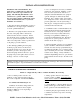
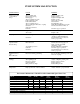
Specifications Model LP301A-5100 U.S. (Metric) Ratings ......................................................... 14.1 GPM ................ (68 LPM) Discharge Pressure ....................................... 4000 PSI .................. (275 bar) RPM ............................................................................................... 1000 RPM Inlet Pressure .................................................................................. Up to 140 PSI Plunger Diameter .............................
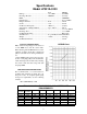
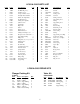
Exploded View - LP301A-5100 4
LP301A-5100 PARTS LIST ITEM 1 2 4 5 6 7 8 9 10 11 12 13 14 15 16 17 20 20A 20B 21 22 23 24 24A 24B 25 28 29A 29B 29C 29D PART 07759 13000 06085 07104 07186 07187 06086 01009 08093 08094 12137 07182 07111 07112 07113 08095 07116 07117 13001 07118 13242 13243 13340 13277 13278 13341 13232 07125 07127 07131-0100 07755-0100 DESCRIPTION QTY Crankcase 1 Oil Filler Plug Assy... 1 Crankcase Cover 1 O-ring, Crankcase Cover 1 Oil Sight Glass w/Gasket 1 Gasket (For Sight Glass) 1 Oil Dipstick Assy.
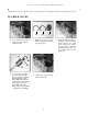
LP301A-5100 REPAIR INSTRUCTIONS NOTE: Always take time to lubricate all metal and non-metal parts with a light film of oil before reassembling. This step will help ensure proper fit, at the same time protecting the pump non-metal parts (elastomers) from cutting and scoring. TO CHECK VALVES 44B 1) Loosen and remove tension plugs (48) with a 36mm socket wrench. 44A 45 2) Remove the support ring (44B), o-ring (44A) and tension spring (45).
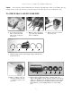
LP301A-5100 REPAIR INSTRUCTIONS NOTE: Always take time to lubricate all metal and non-metal parts with a light film of oil before reassembling. This step will help ensure proper fit, at the same time protecting the pump non-metal parts (elastomers) from cutting and scoring. TO CHECK SEALS AND PLUNGER PIPE 6) Loosen the 8 nuts (49A) with a 19mm socket and pull off valve casing (43) to the front. 39 39A 7) Remove the seal sleeve (35) from the manifold and /or crankcase.
LP301A-5100 REPAIR INSTRUCTIONS 29B 29D 29C Weep Hole 12) Check plunger surface (29B). If plunger pipe is worn out, loosen tension screws (29C) with a 15mm socket and pull off plunger pipe to the front. Clean front surface of plunger (29B) thoroughly. Apply a small drop of locktite to tension screw. Put a new crush washer (29D) onto tension screw. Put a thin coat of glue (Loctite) on the ring (or ceramic plunger side) and tighten screw to 265 in.-lbs.
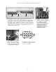
LP301A-5100 REPAIR INSTRUCTIONS TO DISMANTLE GEAR END After removing valve casing (43) and plunger pipe (29B), drain the oil. Remove the gear cover (4) and both bearing covers (14). Loosen connecting rod screws (24A) and push the front of the connecting rod (24) forward as far as possible into the crosshead guide. IMPORTANT! Connecting rods (24) are marked for identification. Do not twist connecting rod halves. Connecting rod is to be reinstalled in the same position on shaft journals.
PUMP SYSTEM MALFUNCTION MALFUNCTION CAUSE REMEDY The Pressure and/ or the Delivery Drops Worn packing seals Broken valve spring Belt slippage Worn or Damaged nozzle Fouled discharge valve Fouled inlet strainer Worn or Damaged hose Worn or Plugged relief valve on pump Cavitation pump for restrictions Unloader Replace packing seals Replace spring Tighten or Replace belt Replace nozzle Clean valve assembly Clean strainer Repair/Replace hose Clean, Reset, and Replace worn parts Check suction lines on inlet
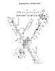
LP301A-5100 DIMENSIONS - Inches (mm) 11
GIANT INDUSTRIES LIMITED WARRANTY Giant Industries, Inc. pumps and accessories are warranted by the manufacturer to be free from defects in workmanship and material as follows: 1. For portable pressure washers and car wash applications, the discharge manifolds will never fail, period. If they ever fail, we will replace them free of charge.