Model MP4130HT(C) Triplex Ceramic Plunger Pump Operating Instructions/ Repair and Service Manual Contents: Installation Instructions: Pump Specifications: Exploded View: Parts List / Kits: Repair Instructions: Torque Specifications: Trouble Shooting: Dimensions: Warranty Information: page 2 pages 3 page 4 page 5 page 6-10 page 10 page 11 back page back page
INSTALLATION INSTRUCTIONS Installation of the Giant Industries, Inc., pump is not a complicated procedure, but there are some basic steps common to all pumps. The following information is to be considered as a general outline for installation. If you have unique requirements, please contact Giant Industries, Inc. or your local distributor for assistance. NPSHR (FT-HEAD) The MP4130HT has been especially constructed for pumping hot water e.g. steam boiler storage.
Specifications Model MP4130HT(C) Volume ....................................................................................................... Up to 629 GPH (10.5 GPM) Discharge Pressure ..................................................................................... Up to 1200 PSI Inlet Pressure............................................................................................See NPSHR chart (pg.2) Speed ........................................................................................
Exploded View - MP4130HT(C) 4
MP4130HT(C) PARTS LIST ITEM PART# DESCRIPTION 1 06100 Crankcase 2 13000 Oil Filler Plug Assembly 4 07243 Cover, Crankcase 5 07244 O-Ring 8 01008 Oil Dip Stick Assembly 9 01009 O-Ring, Dip Stick 10 01010 Screw, Crankcase Cover 11 01011 Spring Washer 12 07109 Oil Drain Plug, G 1/2" 13 07182 Gasket 14 07245 Bearing Cover 15 07247 Seal, Crankshaft 16 07627 O-Ring 17 07114 Hex Screw, Bearing Cover 20 07248 Roller Bearing, Tapered 20A 07249 Fitting Disc 21 07250 Shaft Protector 22 07251 Crankshaft 23 07252 Key 24
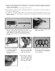
REPAIR INSTRUCTION - MP4130HT(C) Disassembly sequence of the GIANT MP4130HT(C) Series Pumps 1. With a 27mm wrench, remove the three discharge plugs (#48) and three inlet plugs (#42A) from the manifold (#43). 2. 47 44A 46 45 Inspect the plug o-rings (#48A and #42B) and replace as necessary. 44 4. Inspect all parts, especially the seating surface of the valve plate (#45), and replace as necessary. 6.
36 8. From the back of the manifold (#43), remove the packing assembly (#'s 42, 41, 40, and 39) by tapping assembly out from the back to the front. 10. Note: The following procedure is only necessary if a stud bolt (#49) has been damaged and must be replaced. To remove the manifold studs (#49), place a stud nut (#50), lock washer (#50A), and second nut on each stud. Tighten the nuts against each other.
Gear End Disassembly Note: Make certain that the plungers (29B) have been removed before starting the following sequence. 12. Make sure the oil is drained from the pump before removing the crankcase cover (#4). Remove all screws (#10). Inspect the crankcase cover o-ring (#5) for damage and replace it as necessary. 13. Remove the connecting rod screws and washers (#'s 24A and 24B) with a 6mm allen wrench. Remove the back halves of each connecting rod (#24) .
29. Replace any shims (#20A) and position the bearing cover (#14) as before. Tighten the bearing cover bolts (#17) evenly to position the bearing race. Torque the bolts to 125 inch-pounds. Once the crankshaft reassembly is complete, oil the crankshaft races freely before replacing the connecting rod (#24) end caps. 30. Reassemble the connecting rods (#24), matching the numbered (or colored) halves. Torque the connecting rod bolts (#24A) to 250 inch-pounds. 31.
37. Place the entire discharge assembly into discharge port making certain the assembly is properly seated. Install discharge plug (#48) and hand tighten. 38. Reassemble the inlet valve assembly in the reverse order of step #7. Make certain all the components are press fit together and that the spring retainer (#54) is slightly counter sunk in the valve housing (#52). Grease the o-ring (#53) and install it on to the valve housing. Reinstall the entire inlet valve assembly into the manifold (#43).
PUMP SYSTEM MALFUNCTION MALFUNCTION CAUSE REMEDY The Pressure and/or the Delivery Drops Worn packing seals Broken valve spring Belt slippage Worn or Damaged nozzle Fouled discharge valve Fouled inlet strainer Worn or Damaged hose Worn or Plugged relief valve on pump Cavitation Unloader Replace packing seals Replace spring Tighten or Replace belt Replace nozzle Clean valve assembly Clean strainer Repair/Replace hose Clean, Reset, and Replace worn parts Check suction lines on inlet of pump for restrictio
MP4130HT(C) DIMENSIONS (mm) GIANT INDUSTRIES LIMITED WARRANTY Giant Industries, Inc. pumps and accessories are warranted by the manufacturer to be free from defects in workmanship and material as follows: 1. For portable pressure washers and car wash applications, the discharge manifolds will never fail, period. If they ever fail, we will replace them free of charge.