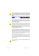
When you installing AGP card, please make sure the following notice is fully understood and practiced. If your AGP card has "AGP 4X/8X (1.5V) notch"(show below), please make sure your AGP card is AGP 4X/8X. AGP 4 X/8 X notc h Caution: AGP 2X card is not supported by nVIDIA® nForce™ 2 400. You might experience system unable to boot up normally. Please insert an AGP Pro 4X/8X card. Example 1: Diamond Vipper V770 golden finger is compatible with 2X/4X mode AGP slot. It can be switched between AGP 2X(3.
The author assumes no responsibility for any errors or omissions that may appear in this document nor does the author make a commitment to update the information contained herein. Third-party brands and names are the property of their respective owners. Please do not remove any labels on motherboard, this may void the warranty of this motherboard. Du e to rapid ch an ge in tec hno lo gy, some of the specifications might be out of date before publication of this booklet. 7n400e_1001_f.
Declaration of Conformity We, Manufacturer/Importer (full address) G.B.T.
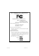
DECLARATION OF CONFORMITY Per FCC Part 2 Section 2.1077(a) Responsible Party Name: G.B.T. INC. (U.S.A.) Address: 17358 Railroad Street City of Industry, CA 91748 Phone/Fax No: (818) 854-9338/ (818) 854-9339 hereby declares that the product Product Name: Motherboard Model Number: GA-7N400E Conforms to the following specifications: FCC Part 15, Subpart B, Section 15.107(a) and Section 15.109(a), Class B Digital Device Supplementary Information: This device complies with part 15 of the FCC Rules.
GA-7N400E(-L) AMD Socket A Processor Motherboard USER'S MANUAL AMD Athlon™/ Athlon™ XP / Duron™ Socket A Processor Motherboard Rev. 1001 12ME-7N400E-1001 7n400e_1001_q.
English Table of Content Item Checklist ......................................................................................... 4 Chapter 1 Introduction ............................................................................ 5 Features Summary ...................................................................................... 5 GA-7N400E(-L) Motherboard Layout .......................................................... 7 Block Diagram - GA-7N400E(-L) ...............................................
Power Management Setup ....................................................................... 46 PnP/PCI Configurations ............................................................................. 49 PC Health Status ........................................................................................ 50 Frequency/Voltage Control ........................................................................ 52 Load Fail-Safe Defaults ...........................................................................
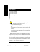
English Item Checklist The GA-7N400E(-L) motherboard CD for motherboard driver & utility The GA-7N400E(-L) user's manual Quick PC Installation Guide IDE cable x 1 / Floppy cable x 1 2 Port USB Cable x 1 I/O Shield Motherboard Settings Label ATX 12V Cable (*) 1. 2. 3. 4. 5. Computer motherboards and expansion cards contain very delicate Integrated Circuit (IC) chips. To protect them against damage from static electricity, you should follow some precautions whenever you work on your computer.
Features Summary 30.5cm x 24.4cm ATX size form factor, 4 layers PCB Socket A processor for AMD Athlon™ / Athlon™ XP / Duron™ (K7) 128K L1 & 256K/64K L2 cache on die 400/333/266/200 MHz FSB Supports 1.4GHz and faster nVIDIA® nForce™ 2 400 Memory/AGP/ PCI Controller (PAC) nVIDIA® nForce™ 2 MCP Integrated Peripheral Controller (PSIPC) 4 184-pin DDR DIMM sockets Supports 128MB/256MB/512MB/1GB unbuffered DRAM Supports up to 3GB DRAM (Max) Supports only 2.
English On-Board LAN(*) On-Board Sound PS/2 Connector BIOS Additional Features Overclocking Builit in Realtek 8100C 1 RJ45 port Realtek ALC650 CODEC Line Out / 2 front speaker Line In / 2 rear speaker (by s/w switch) Mic In / center & subwoofer (by s/w switch) SPDIF In / Out CD In / AUX In / Game port PS/2 Keyboard interface and PS/2 Mouse interface Licensed AWARD BIOS Supports Q-Flash PS/2 Keyboard power on by password PS/2 Mouse power on External Modem wake
English GA-7N400E(-L) Motherboard Layout CLK_RATIO KB_MS ATX_12V FDD nVIDIA ® nForce ™ 2 400 AUDIO AGP IDE1 IDE2 DDR4 2X_DET RTL8100C* DDR3 DDR1 F_AUDIO CLK_SW DDR2 USB LAN(*) COM B GA-7N400E LPT SOCKET A ATX RAM_LED COM A USB CPU_FAN SYS_FAN nVIDIA® ™ nForce 2 MCP PCI1 CD_IN IT8712F -L CODEC PCI2 SUR_CEN PCI3 AUX_IN MAIN BIOS BAT PCI4 CI PCI5 F_USB SPDIF_IO F_PANEL IR GAME INFO_LINK PWR_LED (*)For GA-7N400E-L only. -7- 7n400e_1001_q.
English Block Diagram - GA-7N400E(-L) AMD-K7™ AGP 4X/8X CPUCLK+/- (100/133/166/200MHz) CPU AGPCLK (66MHz) System Bus 400/333/266/200MHz 400/333/266/200MHz nVIDIA® nForce ™ 2 400 5 PCI DDR RAM RJ45(*) 12 MHz 14.318 MHz RTL8100C (*) BIOS nVIDIA® nForce ™ 2 MCP IR Game Port LPC BUS Floppy IT8712 AC97 Link LPT Port PS/2 KB/Mouse 24 MHz LINE-OUT PCICLK (33MHz) MIC LINE-IN AC97 CODEC 6 USB Ports 33 MHz 2 COM Ports ATA33/66/100/133 IDE Channels (*)For GA-7N400E-L only.
English Chapter 2 Hardware Installation Process To set up your computer, you must complete the following steps: Step 1- Set system jumper (CLK_SW)& (CLK_RATIO) Step 2- Install the Central Processing Unit (CPU) Step 3- Install memory modules Step 4- Install expansion cards Step 5- Connect ribbon cables, cabinet wires, and power supply Step 1 Step 3 Step 2 Step 5 Step 5 Step 4 Congratulations! You have accomplished the hardware installation! Turn on the power supply or connect the power cable to the powe
English Step 1: Set System Jumper (CLK_SW) & (CLK_RATIO) The clock ratio can be switched by CLK_RATIO and refer to below table.The system bus frequency can be switched at 100MHz and auto by adjusting CLK_SW. O: ON / X :OFF CLK_RATIO Default Setting : Auto (X X X X X X) CLK_RATIO 6 5 4 3 2 1 Default Setting : OFF CLK_SW ON ON CLK_SW ON OFF OFF AUTO 100MHz AUTO : Supports FSB 400/333/266 MHz CPU 100MHz : Fix FSB 200MHz CPU You must set CLK_SW to 100MHz when you used FSB 200MHz CPU.
Before installing the processor, adhere to the following warning: 1. Please make sure the CPU type is supported by the motherboard. 2. If you do not match the CPU socket Pin 1 and CPU cut edge well, it will cause improper installation. Please change the insert orientation. Step 2-1: CPU Installation CPU Top View CPU Bottom View Pin1 indicator Socket Actuation Lever 1 Pull up the CPU socket lever and up to 90-degree angle. 2.
English Step 2-2: CPU Cooling Fan Installation Before installing the CPU cooling fan, adhere to the following warning: 1. Please use AMD approved cooling fan. 2. We recommend you to apply the thermal tape to provide better heat conduction between your CPU and cooling fan. 3. Make sure the CPU fan power cable is plugged in to the CPU fan connector, this completes the installation. Please refer to CPU cooling fan user's manual for more detail installation procedure. 1.
Before installing the memory modules, adhere to the following warning: 1. When DIMM LED is ON, do not install / remove DIMM from socket. 2. Please note that the DIMM module can only fit in one direction due to the one notch. Wrong orientation will cause improper installation. Please change the insert orientation. The motherboard has 4 dual inline memory module (DIMM) sockets, but it can only support a maximum of 4 banks of DDR memory.
English 1. The DIMM socket has a notch, so the DIMM memory module can only fit in one direction. 2. Insert the DIMM memory module vertically into the DIMM socket. Then push it down. 3. Close the plastic clip at both edges of the DIMM sockets to lock the DIMM module. Reverse the installation steps when you wish to remove the DIMM module.
1. Read the related expansion card's instruction document before install the expansion card into the computer. 2. Remove your computer's chassis cover, screws and slot bracket from the computer. 3. Press the expansion card firmly into expansion slot in motherboard. 4. Be sure the metal contacts on the card are indeed seated in the slot. 5. Replace the screw to secure the slot bracket of the expansion card. 6. Replace your computer's chassis cover. 7.
English Step 5: Connect ribbon cables, cabinet wires and power supply Step 5-1: I/O Back Panel Introduction w u y x v GA-7N400E-L y w u v x GA-7N400E u PS/2 Keyboard and PS/2 Mouse Connector PS/2 Mouse Connector This connector supports standard PS/2 keyboard and PS/2 mouse.
According to your motherboard, please see the following descriptions for the devices. Device like printer can be connected to Parallel port; mouse and modem etc. can be connected to Serial ports. COM1 COM2 Serial Port (9 pin Male) y Audio Connectors Line In (Rear Speaker) Line Out (Front Speaker) MIC In (Center and Subwoofer) After install onboard audio driver, you may connect speaker to Line Out jack, microphone to MIC In jack. Device like CD-ROM,walkman etc. can be connected to Line-In jack.
English Step 5-2: Connectors Introduction 1 10 3 5 2 6 11 12 4 13 15 8 16 14 21 17 19 18 9 20 7 1) ATX_12V 2) ATX 3) CPU_FAN 12) F_AUDIO 13) SUR_CEN 14) SPDIF_IO 4) 5) 6) 7) SYS_FAN FDD IDE1 / IDE2 F_PANEL 15) 16) 17) 18) 8) 9) 10) 11) BAT PWR_LED RAM_LED 2X_DET 19) GAME 20) INFO_LINK 21) CI GA-7N400E(-L) Motherboard 7n400e_1001_q.
English 1) ATX_12V (+12V Power Connector) This connector (ATX_12V) supplies the CPU operation voltage (Vcore). If this "ATX_12V connector" is not connected, system cannot boot. Pin No. 1 1 3 2 4 Definition GND 2 GND 3 +12V 4 +12V 2) ATX (ATX Power) AC power cord should only be connected to your power supply unit after ATX power cable and other related devices are firmly connected to the mainboard. Pin No. 11 20 - 19 - 7n400e_1001_q.p65 19 1 10 Definition 1 3.3V 2 3 3.
English 3) CPU_FAN (CPU Fan Connector) Please note, a proper installation of the CPU cooler is essential to prevent the CPU from running under abnormal condition or damaged by overheating. The CPU fan connector supports Max. current up to 600 mA. Pin No. 1 Definition 1 GND 2 3 +12V Sense 4) SYS_FAN (System Fan Connector) This connector allows you to link with the cooling fan on the system case to lower the system temperature. Pin No. 1 GA-7N400E(-L) Motherboard 7n400e_1001_q.
Please connect the floppy drive ribbon cables to FDD. It supports 360K, 1.2M, 720K, 1.44M and 2.88M bytes floppy disk types. The red stripe of the ribbon cable must be the same side with the Pin1. 34 33 2 1 6) IDE1 / IDE2 (IDE1 / IDE2 Connector) Important Notice: Please connect first hard disk to IDE1 and connect CD-ROM to IDE2. The red stripe of the ribbon cable must be the same side with the Pin1. 40 39 2 1 IDE2 - 21 - 7n400e_1001_q.
Please connect the power LED, PC speaker, reset switch and power switch etc. of your chassis front panel to the F_PANEL connector according to the pin assignment above.
English 8) BATTERY + CAUTION Danger of explosion if battery is incorrectly replaced. Replace only with the same or equivalent type recommended by the manufacturer. Dispose of used batteries according to the manufacturer's instructions. If you want to erase CMOS... 1. Turn OFF the computer and unplug the power cord. 2. Remove the battery, wait for 30 second. 3. Re-install the battery. 4. Plug the power cord and turn ON the computer.
Do not remove memory modules while RAM_LED is on. It might cause short or other unexpected damages due to the stand by voltage. Remove memory modules only when AC power cord is disconnected. + English 10) RAM_LED _ 11) 2X_DET When an AGP 2X (3.3V) card is installed the 4X_AGP will light up, indicating a non-supported graphics card is inserted. Informing users that system might not boot up normally due to AGP 2X (3.3V) is not supported by the chipset. _ 7n400e_1001_q.
If you want to use Front Audio connector, you must remove 5-6, 9-10 Jumper. In order to utilize the front audio header, your chassis must have front audio connector. Also please make sure the pin assigment on the cable is the same as the pin assigment on the MB header. To find out if the chassis you are buying support front audio connector, please contact your dealer.Please note, you can have the alternative of using front audio connector or of using rear audio connector to play sound. Pin No.
English 14) SPDIF_IO (SPDIF In / Out Connector) The SPDIF output is capable of providing digital audio to external speakers or compressed AC3 data to an external Dolby Digital Decoder. Use this feature only when your stereo system has digital input function. Use SPDIF IN feature only when your device has digital output function. Be careful with the polarity of the SPDIF_IO connector.
English 16) AUX_IN (AUX In Connector) Connect other device (such as PCI TV Tunner audio out) to the connector. 1 Pin No. Definition 1 2 AUX-L GND 3 GND 4 AUX-R 17) F_USB (Front USB Connector, Yellow) Be careful with the polarity of the front USB connector. Check the pin assignment while you connect the front USB cable. Please contact your nearest dealer for optional front USB cable. Be careful with the polarity of the F_USB connector.
English 18) IR Make sure the pin 1 on the IR device is aling with pin one the connector. To enable the IR function on the board, you are required to purchase an option IR module. Be careful with the polarity of the IR connector. For optional IR cable, please contact your local dealer. IR 1 Pin No. 1 5 Definition VCC(+5V) 2 No Pin 3 IR Data Input 4 5 GND IR Data Output 19) GAME (Game Connector) This connector supports joystick, MIDI keyboard and other relate audio devices.
This connector allows you to connect some external devices to provide you extra function. Check the pin assignment while you connect the external device cable. Please contact your nearest dealer for optional external device cable. Pin No. 1 2 1 10 9 Definition SMBCLK 2 VCC 3 SMBDATA 4 5 GPIO GND 6 GND 7 No Pin 8 9 NC +12V 10 +12V 21) CI (CASE OPEN) This 2-pin connector allows your system to enable or disable the "Case Open" item in BIOS, if the system case begin remove.
English GA-7N400E(-L) Motherboard 7n400e_1001_q.
BIOS Setup is an overview of the BIOS Setup Program. The program that allows users to modify the basic system configuration. This type of information is stored in battery-backed CMOS RAM so that it retains the Setup information when the power is turned off. ENTERING SETUP Powering ON the computer and pressing immediately will allow you to enter Setup. If you require more advanced BIOS settings, please go to "Advanced BIOS" setting menu.
English GETTING HELP Main Menu The on-line description of the highlighted setup function is displayed at the bottom of the screen. Status Page Setup Menu / Option Page Setup Menu Press F1 to pop up a small help window that describes the appropriate keys to use and the possible selections for the highlighted item. To exit the Help Window press . The Main Menu (For example: BIOS Ver. : E2) Once you enter Award BIOS CMOS Setup Utility, the Main Menu (Figure 1) will appear on the screen.
AdvancedChipset Features English l This setup page includes all the items of Chipset special enhanced features. l Integrated Peripherals This setup page includes allonboard peripherals. l PowerManagement Setup l PnP/PCI Configurations This setup page includes all the items of Green function features. This setup page includes all the configurations of PCI & PnP ISA resources.
English Standard CMOS Features CM OS Setup Utility-Copyright (C) 1984-2003 Award Software Standard CM OS Features Date (mm:dd:yy) Tue, May 20 2003 Time (hh:m m:ss) 22:31:24 Item Help Menu Level u Change the day, month, }IDE Prim ary M aster [None] }IDE Primary Slave [None] year }IDE Secondary M aster [None] }IDE Secondary Slave [None] Sun. to Sat. Drive A [1.44M, 3.5"] Drive B [None] Jan. to Dec.
The times format in . The time is calculated base on the 24-hour military-time clock. For example, 1 p.m. is 13:00:00. IDE Primary Master, Slave / IDE Secondary Master, Slave The category identifies the types of hard disk from drive C to F that has been installed in the com puter. There are two types: auto type, and manual type. Manual type is user-definable; Auto type which will automatically detect HDD type.
English Floppy 3 Mode Support (for Japan Area) Disabled Normal Floppy Drive. (Default value) Drive A Drive A is 3 mode Floppy Drive. Drive B Drive B is 3 mode Floppy Drive. Both Drive A & B are 3 m ode Floppy Drives. Halt on The category determines whether the computer will stop if an error is detected during power up. NO Errors The system boot will not stop for any error that may be detected and you will be prompted.
English Advanced BIOS Features CM OS Setup Utility-Copyright (C) 1984-2003 Award Software Advanced BIOS Features First Boot Device [Floppy] Item Help Second Boot Device [HDD-0] Menu Level u Third Boot Device [CDROM ] Select onboard RAID or SCSI PCI SCSI boot rom [Disabled] order x SATA/RAID/SCSI Boot Order Boot Up Floppy Seek Flexible AGP 8X [Auto] Init Display First [PCI] higf: Move Enter:Select +/-/PU/PD: Value F10: Save ESC:Exit F5: Previous Values F6: Fail-Safe Defaults F1: General H
English SATA/RAID/SCSI Boot Order This function will available when Boot up device set at "SCSI". This feature allows you to select the boot order Serial ATA, RAID or SCSI device. SCSI Select your boot device priority by PCI SCSI. RAID Select your boot device priority by RAID. SATA A Select your boot device priority by Serial ATA. Boot Up Floppy Seek During POST, BIOS will determine the floppy disk drive installed is 40 or 80 tracks. 360K type is 40 tracks 720K, 1.2M and 1.44M are all 80 tracks.
English Advanced Chipset Features CM OS Setup Utility-Copyright (C) 1984-2003 Award Software Advanced Chipset Features System Performance [Normal] Item Help Menu Level u FSB Frequency [133MHz] Memory Frequency By SPD Resulting Frequency 266MHz [Norm al] - Use the AGP Frequency [Normal] most stable settings. [Turbo] -Use over colocked settings for higher performance but with higher risk of instability.
English MemoryFrequency By SPD Set m emory frequency by SPD. (Default Value) 50%~200% Set the m emory frequency manually. Auto Set the best m emory frequency for system. Incorrect using it m ay cause your system to fail. For power End-User use only! Resulting Frequency The value depends on FSB/M emory Frequency. AGP Frequency Normal Set the best AGP frequency for system. (Default Value) 50MHz ~ 100MHz Set the AGP frequency manually. Incorrect using it m ay cause your system broken.
English Integrated Peripherals CM OS Setup Utility-Copyright (C) 1984-2003 Award Software On-Chip Prim ary PCI IDE Integrated Peripherals [Enabled] Item Help Menu Level u On-Chip Secondary PCI IDE [Enabled] USB Host Controller [V1.1+V2.
English On-Chip Primary PCI IDE Enabled Enable onboard 1st channel IDE port. (Default value) Disabled Disable onboard 1st channel IDE port. On-Chip Secondary PCI IDE Enabled Enable onboard 2nd channel IDE port. (Default value) Disabled Disable onboard 2nd channel IDE port. USB Host Controller Disabled Disable USB controller. V1.1+V2.0 Set USB controller at USB1.1 and USB2.0. (Default Value) V1.1 Set USB controller at USB1.1. USB KeyboardSupport Enabled Enable USB Keyboard Support.
English Onboard LAN Boot ROM(*) This function decide whether to invoke the boot ROM of the onboard LAN chip. Enabled Enable Onboard LAN chip function. Disabled Disable this function. (Default value) Onboard Serial Port 1 Disabled Disable onboard Serial port 1. 3F8/IRQ4 Enable onboard Serial port 1 and address is 3F8, using IRQ4. (Default value) 2F8/IRQ3 Enable onboard Serial port 1 and address is 2F8, using IRQ3. 3E8/IRQ4 Enable onboard Serial port 1 and address is 3E8, using IRQ4.
English UR2Duplex Mode This feature allows you to seclect IR m ode. This function will available when "UART Mode Select" doesn't set at "Normal" nor "SCR". Half IR Function Duplex Half. (Default Value) Full IR Function Duplex Full. Onboard Parallel port This feature allows you to select from a given set of parameters if the parallel port uses the onboard I/O controller. Disabled Disable onboard LPT port. 378/IRQ7 Enable onboard LPT port and address is 378, using IRQ7.
Disabled Disable this function. 330 Set Midi Port Address to 330. (Default Value) 300 Set Midi Port Address to 300. English Midi Port Address Midi Port IRQ 5 Set M idi Port IRQ to 5. 10 Set Midi Port IRQ to 10. (Default Value) - 45 - 7n400e_1001_b.
English Power Management Setup CM OS Setup Utility-Copyright (C) 1984-2003 Award Software Power M anagement Setup ACPI Suspend Type [S1(POS)] Item Help Soft-Off by PWR-BTTN [Instant-off] Menu Level u PM E Event Wake Up [Enabled] [S1] ModemRingOn [Enabled] Set suspend type to S3 Resume by USB [Disabled] Power On Suspend under ACPI OS Resume by Alarm [Disabled] x Date (of Month) Alarm Ever yday x Tim e (hh:mm :ss) Alarm 0:0:0 [S3] [Disabled] Set suspend type to Power On by Mouse Power
Disabled Disable this function. Enabled Enable PME Event Wake up. (Default Value) English PMEEvent Wake Up ModemRingOn An incoming call via modem can awake the system from any suspend state . Disabled Disable Modem Ring on function. Enabled Enable Modem Ring on function. (Default Value) S3 Resume by USB You can resume the system from USB device. Disabled Disable this function. (Default Value) Enabled Enable this function.
English Power OnBy Keyboard This feature allows you to set the m ethod for powering-on the system. The option "Password" allows you to set up to 5 alphanum eric characters to power-on the system. The option "Keyboard 98" allows you to use the standard keyboard 98 to power on the system. Password Enter from 1 to 5 characters to set the Keyboard Power On Password. Disabled Disabled this function.
English PnP/PCI Configurations CM OS Setup Utility-Copyright (C) 1984-2003 Award Software PnP/PCI Configurations PCI 1/PCI 5 IRQ Assignment [Auto] Item Help PCI 2 IRQ Assignment [Auto] Menu Level u PCI 3 IRQ Assignment [Auto] Device(s) using this PCI 4 IRQ Assignment [Auto] INT : Network Cntrlr - Bus 1 Dev 11 Func 0 higf: Move Enter:Select +/-/PU/PD: Value F10: Save ESC:Exit F5: Previous Values F6: Fail-Safe Defaults F1: General Help F7: Optimized Defaults Figure 7: PnP/PCI Configurations
English PC Health Status CM OS Setup Utility-Copyright (C) 1984-2003 Award Software PC Health Status Reset Case Open Status [Disabled] Item Help Case Opened Yes Menu Level u Vcore OK [Disabled] DDR25V OK Don't reset case +3.
English Current Voltage (V) Vcore / DDR25V / +3.3V / +5V / +12V Detect system 's voltage status autom atically. Current System Temperature Detect System temperature autom atically. Current CPU Temperature Detect CPU temperature autom atically. Current CPU/SYSTEMFAN Speed (RPM) Detect CPU/SYSTEM Fan speed status automatically. CPU Warning Temperature 60oC / 140o F 70oC / 158o F 80oC / 176o F 90oC / 194o F 8Disabled Monitor CPU Tem p. at 60oC / 140oF. Monitor CPU Tem p. at 70oC / 158oF.
English Frequency/Voltage Control CM OS Setup Utility-Copyright (C) 1984-2003 Award Software Frequency/Voltage Control VCORE OverVoltage Control [Normal] Item Help DIMM OverVoltage Control [Normal] Menu Level u AGP OverVoltage Control [Normal] higf: Move Enter:Select +/-/PU/PD: Value F10: Save ESC:Exit F5: Previous Values F6: Fail-Safe Defaults F1: General Help F7: Optimized Defaults Figure 9: Frequency/Voltage Control VCORE OverVoltage Control Increase VCORE voltage may get stable for Over_Cl
English Load Fail-Safe Defaults CM OS Setup Utility-Copyright (C) 1984-2003 Award Software } Standard CM OS Features } Frequency/Voltage Control } Advanced BIOS Features Load Fail-Safe Defaults } Advanced Chipset Features Load Optimized Defaults Set?Supervisor Password } Integrated Peripherals Load Fail-Safe Defaults (Y/N) Y } Power M anagement Setup Set User Password } PnP/PCI Configurations Save & Exit Setup } PC Health Status Exit Without Saving higf: Select Item ESC: Quit F8: Dual BIOS / Q-
English Load Optimized Defaults CM OS Setup Utility-Copyright (C) 1984-2003 Award Software } Standard CM OS Features } Frequency/Voltage Control } Advanced BIOS Features Load Fail-Safe Defaults } Advanced Chipset Features Load Optimized Defaults ?Y Set Supervisor Password } Integrated PeripheralsLoad Optimized Defaults (Y/N) } Power M anagement Setup Set User Password } PnP/PCI Configurations Save & Exit Setup } PC Health Status Exit Without Saving higf: Select Item ESC: Quit F8: Dual BIOS / Q-
English Set Supervisor/User Password CM OS Setup Utility-Copyright (C) 1984-2003 Award Software } Standard CM OS Features } Frequency/Voltage Control } Advanced BIOS Features Load Fail-Safe Defaults } Advanced Chipset Features Load Optimized Defaults Enter Password: } Integrated Peripherals Set Supervisor Password } Power M anagement Setup Set User Password } PnP/PCI Configurations Save & Exit Setup } PC Health Status Exit Without Saving higf: Select Item ESC: Quit F8: Dual BIOS / Q-Flash F1
English Save & Exit Setup CM OS Setup Utility-Copyright (C) 1984-2003 Award Software } Standard CM OS Features } Frequency/Voltage Control } Advanced BIOS Features Load Fail-Safe Defaults } Advanced Chipset Features Load Optimized Defaults } Integrated Peripherals Set Supervisor Password Save to CMOS and EXIT (Y/N) ? Y } Power M anagement Setup Set User Password } PnP/PCI Configurations Save & Exit Setup } PC Health Status Exit Without Saving higf: Select Item ESC: Quit F8: Dual BIOS / Q-Fla
English Exit Without Saving CM OS Setup Utility-Copyright (C) 1984-2003 Award Software } Standard CM OS Features } Frequency/Voltage Control } Advanced BIOS Features Load Fail-Safe Defaults } Advanced Chipset Features Load Optimized Defaults } Integrated Peripherals Set Supervisor Password Quit Without Saving (Y/N)? N } Power M anagement Setup Set User Password } PnP/PCI Configurations Save & Exit Setup } PC Health Status Exit Without Saving higf: Select Item ESC: Quit F8: Dual BIOS / Q-Flas
English GA-7N400E(-L) Motherboard 7n400e_1001_b.
English Chapter 4 Technical Reference BIOS Flash Procedure Method 1: Q-Flash Introduction A. What is Q-Flash Utility? Q-Flash utility is a pre-O.S. BIOS flash utility enables users to update its BIOS within BIOS mode, no more fooling around any OS. B. How to use Q-Flash? a. After power on the computer, pressing immediately during POST (Power On Self Test) it will allow you to enter AWARD BIOS CMOS SETUP, then press to enter Q-Flash utility.
English Load BIOS From Floppy !In the A:drive, insert the "BIOS" diskette, then Press Enter to Run. 1 File(s) found XXXX.XX 256K Total Size: 1.39M F5: Refresh Free Size: 1.14M DEL: Delete ESC: Return Main Where XXXX.XX is name of the BIOS file. !Press Enter to Run. Are you sure to update BIOS? [Enter] to contiune Or [ESC] ot abort... !Press Enter to Run. !! COPY BIOS Completed -Pass !! Please press any key to continue Congratulation! You have completed the flashed and now can restart system.
If you don’thave DOS boot disk, we recommend that you used Gigabyte @BIOSTM program to flash BIOS. Follow the setup that showing on the scween to install the Utility. 2.Click"Start"-"Programs""GIGABYTE"-"@BIOS" Press here. 1.Click "@BIOS . (1) Click "P". (2) Click here. 3. Please select @BIOS sever site, then Click "OK". (4) (3) Methods and steps: I. Update BIOS through Internet a. Click "Internet Update" icon b. Click "Update New BIOS" icon c. Select @BIOSTM sever d.
English II. Update BIOS NOT through Internet: a. b. c. d. Do not click "Internet Update" icon Click "Update New BIOS" Please select "All Files" in dialog box while opening the old file. Please search for BIOS unzip file, downloading from internet or any other methods (such as: 7N400E.F1). e. Complete update process following the instruction. III. Save BIOS In the very beginning, there is "Save Current BIOS" icon shown in dialog box. It means to save the current BIOS version. IV.
English @ BIOS Introduction Gigabyte announces @ BIOS Windows BIOS live update utility Have you ever updated BIOS by yourself? Or like many other people, you just know what BIOS is, but always hesitate to update it? Because you think updating newest BIOS is unnecessary and actually you don’tknow how to update it. Maybe not like others, you are very experienced in BIOS updating and spend quite a lot of time to do it. But of course you don’tlike to do it too much.
English Revision 2-/4-/6-Channel HistoryAudio Function Introuction The installation of windows 98SE/2K/ME/XP is very simple. Please follow next step to install the function! Stereo Speakers Connection and Settings: We recommend that you use the speaker with amplifier to acqiire the best sound effect if the stereo output is applied. STEP 1: Connect the stereo speakers or earphone to "Line Out". Line Out STEP 2 : After installation of the audio driver, you'll find an icon on the taskbar's status area.
English 4 Channel Analog Audio Output Mode STEP 1 : Connect the front channels to "Line Out", the rear channels to "Line In". Line Out Line In STEP 2 : After installation of the audio driver, you'll find an icon on the taskbar's status area. Click the audio icon "Sound Effect" from the windows tray at the bottom of the screen. STEP 3 : Select "Speaker Configuration", and choose the "4 channel for 4 speakers out put". Disable "Only SURROUND-KIT", and press "OK".
English Basic 6 Channel Analog Audio Output Mode Use the back audio panel to connect the audio output without any additional module. STEP 1 : Connect the front channels to "Line Out",the rear channels to "Line In", and the Center/Subwoofer channels to "MIC In". Line In MIC In STEP 2 : After installation of the audio driver, you'll find an icon on the taskbar's status area. Click the audio icon "Sound Effect" from the windows tray at the bottom of the screen.
(Audio Combo Kit provides SPDIF output port : optical & coaxis and SURROUND-KIT : Rear R/L & CEN / Subwoofer) SURROUND-KIT access analog output to rear channels and Center/Subwoofer channels. It is the best solution if you need 6 channel output, Line In and MIC at the same time. "SURROUND-KIT" is included in the GIGABYTE unique "Audio Combo Kit" as picture. STEP 1 : Insert the "SURROUND-KIT" in the back of the case , and fix it with the screw. STEP 2 : Connect the "SURROUND-KIT" to SUR_CEN on the M/B.
English STEP 3 : Connect the front channels to back audio panel's "Line Out", the rear channels to SURROUND-KIT's REAR R/L, and the Center/Subwoofer channels to SURROUND-KIT's SUB CENTER. STEP 4 : Click the audio icon "Sound Effect" from the windows tray at the bottom of the screen. STEP 5 : Select "Speaker Configuration", and choose the "6 channels for 5.1 speakers out put". Enable "Only SURROUND-KIT" and press "OK".
English SPDIF Output Device (Optional Device) A "SPDIF output" device is available on the motherboard. Cable with rear bracket is provided and could link to the "SPDIF output" connector (As picture.) For the further linkage to decoder, rear bracket provides coaxial cable and Fiber connecting port. 1. Connect the SPDIF output device to the rear bracket of PC, and fix it with screw. 2. Connect SPDIF device to the motherboard. 3. Connect SPDIF to the SPDIF decoder.
English Xpress Recovery Introduction What is Xpress Recovery? Xpress Recovery utility is an utility for backing up and restoring O.S. partition . If the hard drive can not work properly, you can restore it to the original state. 1. It supports FAT16, FAT32, NTFS Operation System . 2. It does not work when you install Boot Manager . 3. It must be used with IDE hard disk supporting HPA . 4. The first partition must be set as the boot partition.
English b. Xpress Recovery: Xpress Recovery V1.0 (C) Copy Right 2003. GIGABYTE Technilogy CO. , Ltd. 1. Excute Backup Utility 2. Excute Restore Utility 3. Remove Backup Image 4. Exit and Restart 1.Excute Backup Utility: ! Press B to Backup your System or Esc to Exit The Backup utility will scan the system automatically and back it up. The backed up data will be saved as a hidden image . 2.Excute Restore Utility: ! This program will recover your system to factory default. Press R to recover your system.
English GA-7N400E(-L) Motherboard - 72 -
English - 73 - Technical Reference
English GA-7N400E(-L) Motherboard - 74 -
English Revision ChapterHistory 5 Appendix Install Drivers Pictures below are shown in Windows XP Insert the driver CD-title that came with your motherboard into your CD-ROM drive, the driver CD-title will auto start and show the installation guide. If not, please double click the CD-ROM device icon in "My computer", and execute the setup.exe. INSTALL CHIPSET DRIVER This page shows the drivers that need to be installed for the system.
English Driver installation finished ! You have to reboot system ! Item Description n Nvidia System Driver nVIDIA Chipset Driver n USB Patch for WinXP This patch driver can help you to resolve the USB device wake up S3 hang up issue in XP. n RealTek LAN Drive(*) RealTek 10/100 LAN driver for 81xx series chips(*) n RealTek AC97 Codec Driver Realtek Audio Driver n Nvidia USB 2.0 Driver Information nVIDIA USB 2.
This page reveals the value-added software developed by Gigabyte and its worldwide partners.
English SOFTWARE INFORMATION This page list the contects of softwares and drivers in this CD title. HARDWARE INFORMATION This page lists all device you have for this motherboard. CONTACT US Please see the last page for details. GA-7N400E(-L) Motherboard 7n400e_1001_a.
Below is a collection of general asked questions. To check general asked questions based on a specificmotherboardmodel,pleaselogontohttp://tw.giga-byte.com/faq/faq.htm Question 1: I cannot see some options that were included in previous BIOS after updating BIOS. Why? Answer: Some advanced options are hidden in new BIOS version. Please press Ctrl and F1 keys after entering BIOS menu and you will be able to see these options.
English Question 6: Why does system seem unstable after updating BIOS? Answer: Please remember to load Fail-Safe Defaults (Or Load BIOS Defaults) after flashing BIOS. However, if the system instability still remains, please clear CMOS to solve the problem. Question 7: Why do I still get a weak sound after turning up the speaker to the maximum volume? Answer: Please make sure the speaker you are using is equipped with an internal amplifier.
English g AWARD BIOS Beep Codes 1 short: System boots successfully 2 short: CMOS setting error 1 long 1 short: DRAM or M/B error 1 long 2 short: Monitor or display card error 1 long 3 short: Keyboard error 1 long 9 short: BIOS ROM error Continuous long beeps: DRAM error Continuous short beeps: Power error Question 11: How to set in the BIOS in order to bootup from SATA HDDs by either RAID or ATA mode? Answer: Please set in the BIOS as follow: 1.
English Troubleshooting If you encounter any trouble during boot up, please follow the troubleshooting procedures. START Turn off the power and unplug the AC power cable, then remove all of the add-on cards and cables from motherboard. Please make sure motherboard & chassis are not short ? Yes Please isolate the short pin. No Failure has been excluded. Please make sure all jumper settings (such as CPU system bus speed, frequenc y ratio, voltage and etc ) are set properly.
Is memory LED on and CPU fan running? No The problem could be caused by power supply, CPU , memory or CPU /memory socket itself. Yes Failure has been excluded. No Check if there is display. Yes Perhaps your V GA card / VG A slot or monitor is defective. Failure has been excluded. Turn off the system. Reboot after keyboard and mouse have been plugged in. Check if keyboard is working properly. No It is possible that your key board or key board connector is defectiv e.
Customer/Country: Company: Contact Person: E-mail Add. : Model name/Lot Number: BIOS version: Hardware Configuration CPU Phone No.: & English Technical Support/RMA Sheet PCB revision: O.S./A.S.: Mfs. Modelname Size: Driver/Utility: Memory Brand Video Card Audio Card HDD CD-ROM / DVD-ROM Modem Network AMR / CNR Keyboard Mouse Power supply Other Device Problem Description: & GA-7N400E(-L) Motherboard 7n400e_1001_a.
Acronyms ACPI APM AGP Meaning Advanced Configuration and Power Interface Advanced Power Management Accelerated Graphics Port AMR ACR BIOS CPU CMOS CRIMM CNR DMA Audio Modem Riser Advanced Communications Riser Basic Input / Output System Central Processing Unit Complementary Metal Oxide Semiconductor Continuity RIMM Communication and Networking Riser Direct Memory Access DMI DIMM DRM DRAM DDR ECP ESCD ECC Desktop Management Interface Dual Inline Memory Module Dual Retention Mechanism Dynamic Random Acce
English Acronyms Meaning IOAPIC ISA LAN I/O LBA LED MHz MIDI Input Output Advanced Programmable Input Controller Industry Standard Architecture Local Area Network Input / Output Logical Block Addressing Light Emitting Diode Megahertz Musical Instrument Digital Interface MTH MPT NIC OS OEM PAC POST PCI Memory Translator Hub Memory Protocol Translator Network Interface Card Operating System Original Equipment Manufacturer PCI A.G.P.
English - 87 - 7n400e_1001_a.
English GA-7N400E(-L) Motherboard 7n400e_1001_a.
English - 89 - 7n400e_1001_a.
English GA-7N400E(-L) Motherboard 7n400e_1001_a.
English - 91 - 7n400e_1001_a.
English CONTACT US Contact us via the information in this page all over the world. — Taiwan Gigabyte Technology Co., Ltd. Addre ss: No.6, Bau Chiang Road, Hsin-Tien, Taipei Hsien, Taiwan, R.O.C. TEL: 886 (2) 8912-4888 (50 lines) FAX: 886 (2) 8912-4004 E-mail:english@gigabyte.com.tw — The Netherlands Giga-Byte Technology B.V. Add ress: Postbus 1385, 5602 BJ, Eindho ven, The Netherlands Tel: +31 40 290 2088 Fax: +31 40 290 2089 E-mail:info@giga-byte.nl Web Address: http://www.gigabyte.com.tw — USA G.B.T.