7VM333M-RZ AMD Sempron™ /Athlon™ /Athlon™ XP/Duron™ Socket A Processor Motherboard User's Manual Rev. 1004 12ME-VM333MRZ-1004 Copyright © 2004 GIGABYTE TECHNOLOGY CO., LTD Copyright by GIGA-BYTE TECHNOLOGY CO., LTD. ("GBT"). No part of this manual may be reproduced or transmitted in any from without the expressed, written permission of GBT. Trademarks Third-party brands and names are the property of their respec tive owners.
Mother Board 7VM333M-RZ Mar. 17, 2004 Motherboard 7VM333M-RZ Mar.
Preparing Your Computer Computer motherboards and expansion cards contain very delicate Integrated Circuit (IC) chips. To protect them against damage from static electricity, you should follow some precautions whenever you work on your computer. 1. Unplug your computer when working on the inside. 2. Use a grounded wrist strap before handling computer components. If you do not have one, touch both of your hands to a safely grounded object or to a metal object, such as the power supply case. 3.
English Table of Contents Chapter 1 Introduction .............................................................................................. 5 Features Summary ........................................................................................................................ 5 7VM333M-RZ Motherboard Layout.............................................................................................. 6 Block Diagram .....................................................................................
Features Summary CPU Chipset Memory Slots On-Board IDE On-Board Floppy On-Board Peripherals On-Board VGA On-Board LAN On-Board Sound BIOS I/O Control Hardware Monitor Additional Features Overclocking Form Factor — — — — — — — — — — — — — — — — — — — — — — — — — — — — — — — — — — — — — — — Socket A for AMD Sempron™ /Athlon™ XP / Athlon™ / Duron™ processor 200/266/333MHz FSB Supports 1.
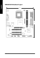
22.3 cm KB_MS LPT COMA ATX FDD CPU_FAN IDE1 BIOS AGP CLR_CMOS VT6103 PCI1 VIA VT8235/ VT8237R PCI2 CD_IN PCI3 CODEC SUR_CEN DDR2 SYS_FAN DDR1 F_AUDIO 7VM333M-RZ Motherboard BAT F_U SB1 F_U SB2 PWR_LED GAME SPDIF JP 1 COMB -6 - F_PANEL IDE2 LAN LINE_IN MIC_IN USB VIA KM266 Pro I T8705 24.
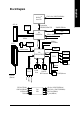
AMD-K7TM Host CPU AGP 4X System Bus 200/266/333Hz FSB VGA Port VIA KM266 Pro 200/266/333MHz DDR HCLK+/- (100/133/166MHz) NBGCLK66 MHz VT6103 66MHz V_Link RJ45 AGPCLK 66MHz 3 PCI CPUCLK+/- (100/133/166MHz) 48 MHz 33 MHz 14.318 MHz BIOS PCI BUS 33MHz VIA LPC BUS VT8235/VT8237R Game Port Floppy IT8705 AC97 Link LPT Port 24 MHz PCICLK (33MHz) USBCLK (48MHz) 14.
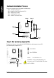
English Hardware Installation Process To set up your computer, you must complete the following steps: Step 1- Set System Jumper (JP1) Step 2- Install the Central Processing Unit (CPU) Step 3- Install Memory Modules Step 4- Install Expansion Cards Step 5- Install I/O Peripherals Cables Step 2 Step 3 Step 5 Step 5 Step 4 Step 1 Step 1: Set System Jumper (JP1) The system bus frequency can be switched at 100/133/166MHz by adjusting system jumper (JP1). (The internal frequency depend on CPU.
Before installing the processor, adhere to the following warning: 1. Please make sure the CPU type is supported by the motherboard. 2. The processor will overheat without the heatsink and/or fan, resulting in permanent irreparable damage. 3. If you do not match the CPU socket Pin 1 and CPU cut edge well, it will cause improper installation. Please change the insert orientation. 4. Apply thermal grease between the processor and cooling fan. 5.
English Step 3: Install Memory Modules Before installing the memory modules, adhere to the following warning: 1. Please note that the DIMM module can only fit in one direction due to the one notch. Wrong orientation will cause improper installation. Please change the insert orientation. The m otherboard has 2 dual inline m emory module (DIMM) sockets. The BIOS will automatically detects memory type and size. To install the memory module, just push it vertically into the DIMM socket.
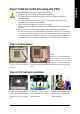
1. Read the relate AGP card's instruction document before install the AGP card into the computer. 2. If your AGP card has "AGP 4X(1.5V) notch"(show below), please make sure your AGP card is AGP 4X(1.5V). 3. Please carefully pull out the small white-drawable bar at the end of the AGP slot when you try to install/ uninstall the AGP card. Please align the AGP card to the onboard AGP slot and press firmly down on the slot. Make sure your AGP card is locked by the small white-drawable bar.
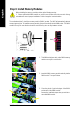
English | Line Out jack Connect the stereo speakers or earphone to this connector. } MIC In jack Microphone can be connect to MIC In jack. After installation of the audio driver, you are able to use 2/4/6-channel audio feature by software selection. You can connect "Front speaker" to "Line Out" jack, Connect "Rear speaker" to "Line In" jack and connect "Center/Subwoofer" to "M IC In" jack.
AC power cord should only be connected to your power supply unit after ATX power cable and other related devices are firmly connected to the mainboard. 11 20 1 Pin No. 1 2 3 4 5 6 7 8 9 10 10 Definition 3.3V 3.3V GND VCC GND VCC Pin No. 11 12 13 14 15 16 GND Power Good 5V SB (s tand by +5V) +12V 17 18 19 20 Definition 3.
English 4) FDD (Floppy Connector) Please connect the floppy drive ribbon cables to FDD. It supports 360K, 1.2M, 720K, 1.44M and 2.88M bytes floppy disk types. The red stripe of the ribbon cable m ust be the sam e side with the Pin1. 34 33 2 1 5) IDE1 / IDE2 (IDE1 / IDE2 Connector) Please connect first hard disk to IDE1 and connect CD-ROM to IDE2. The red stripe of the ribbon cable m ust be the sam e side with the Pin1.
Please connect the power LED, PC speaker, reset switch and power switch etc. of your chassis front panel to the F_PANEL connector according to the pin assignment below.
English 9) SUR_CEN (Surround Center Connector) Please contact your nearest dealer for optional SUR_CEN cable. 1 2 5 6 Pin No. 1 2 3 4 5 6 Definition SUROUTL SUROUTR GND No Pin CENTER_OUT BASS_OUT 10) SPDIF (SPDIF Out Connector) The SPDIF output is capable of providing digital audio to external speakers or compressed AC3 data to an external Dolby Digital Decoder. Use this feature only when your stereo system has digital input function. Be careful with the polarity of the SPDIF connector.
Be careful with the polarity of the COMB connector. Check the pin assignm ent carefully while you connect the COMB cable, incorrect connection between the cable and connector will make the device unable to work or even damage it. For optional COMB cable, please contact your local dealer. 2 1 Pin No. 1 2 3 4 5 6 7 8 9 10 10 9 Definition NDCDBNSINB NSOUTB NDTRBGND NDSRBNRTSBNCTSBNRIBNo Pin 13) GAME (Game Connector) This connector supports joystick, MIDI keyboard and other relate audio devices.
English 15) CLR_CMOS (Clear CMOS) You may clear the CMOS data to its default values by this jumper. To clear CMOS, temporarily shor 12 pin. Default doesn't include the "Shunter" to prevent from improper use this jumper. 1-2 close: Clear CMOS 1 Open: Normal 1 16) BAT (Battery) + CAUTION Danger of explosion if battery is incorrectly replaced. Replace only with the same or equivalent type recommended by the manufacturer. Dispose of used batteries according to the manufacturer's instructions.
BIOS Setup is an ov erv iew of the BIOS Setup Program. The program that allow s users to modify the basic sy stem configuration. This ty pe of information is stored in battery -backed CM OS RAM so that it retains the Setup information w hen the pow er is turned off. ENTERING SETUP Pow ering ON the computer and pressing immediately w ill allow y ou to enter Setup. If y ou require more adv anced BIOS settings, please go to "Adv anced BIOS" setting menu.
English If you can't find the setting you want, please press "Ctrl+F1" to search the advanced option hidden. • Standard CMOS Features This setup page includes all the items in s tandard c ompatible BIOS. • Advanced BIOS Features This setup page includes all the items of Aw ard special enhanced features. • Integrated Peripherals This setup page includes all onboard peripherals. • Power Management Setup This setup page includes all the items of Green func tion features.
CMOS Setup Ut ility-Co pyright (C) 1984 -2004 Aw ard Soft ware Stan dard CM OS Feat ures } } } } Date (mm:dd :yy) Time (hh:mm :ss) Thu, Jan 1 5 2004 22:3 1:24 IDE IDE IDE IDE [No ne] [No ne] [No ne] [No ne] P rimary M aster P rimary S lave S econdary M aster S econdary Slave Driv e A Driv e B Flopp y 3 Mode S uport [1.44M, 3.
English Drive A / Dri ve B The category identifies the ty pes of floppy disk driv e A or driv e B that has been installed in the computer. None No floppy driv e installed 360K, 5.25" 5.25 inch PC-ty pe standard driv e; 360K by te capacity . 1.2M, 5.25" 5.25 inch AT-ty pe high-density driv e; 1.2M by te capacity (3.5 inch w hen 3 Mode is Enabled). 720K, 3.5" 3.5 inch double-sided driv e; 720K by te capacity 1.44M, 3.5" 3.5 inch double-sided driv e; 1.44M by te capacity . 2.88M, 3.5" 3.
CMOS Setup Ut ility-Co pyright (C) 1984 -2004 Aw ard Soft ware Adva nced BI OS Feat ures Firs t Boot D evice Seco nd Boot D evice Thir d Boot D evice Pas sword C heck [Flo ppy] [HDD -0] [CDR OM] [Set up] Item Help Menu L evel} Selec t Boot D evice prio rity [Flo ppy] Boot from fl oppy [LS1 20] Boot from L S120 [HDD -0] Boot from Firs t HDD [HDD -1] Boot from Secon d HDD higf: M ove Enter: Select F5: P revious V alues +/-/ PU/PD: V alue F10: Save F6: Fa il-Save De fault ESC: Exit F1: General Help F7: Op
English Integrated Peripherals CMOS Setup Ut ility-Co pyright (C) 1984 -2004 Aw ard Soft ware Inte grated Periphe rals On-Ch ip IDE Cha nnel0 On-Ch ip IDE Cha nnel1 AC97 Audio VIA Onboard LAN USB 1 .1 Contr oller USB 2 .
Enabled Disabled English USB Mouse Support Enable USB mouse support. Disable USB m ouse support. (Default v alue) On-Chi p LAN Boot ROM This function decide w hether to inv oke the boot ROM of the onboard LAN chip. Disabled Disable this function. (Default Value) Enabled Enable this func tion. Onboard Serial P ort 1 Auto 3F8/ IRQ4 2F8/ IRQ3 3E8/ IRQ4 2E8/ IRQ3 Disabled BIOS w ill autom atically s etup the port 1 address. Enable onboard Serial port 1 and address is 3F8.
English Power Management Setup CMOS Setup Ut ility-Co pyright (C) 1984 -2004 Aw ard Soft ware Powe r Manag ement S etup ACPI Suspend Type x USB D evice Wa ke-Up fr om S3 Power LED in S1 state Soft- Off by P WRBTN AC B ack Func tion Keybo ard Powe r On Mous e Powe r On PME E vent Wak e Up ModemR ingOn/Wake OnLan Resu me by A larm x Date ( of Month) Alarm x Time ( hh:mm:ss) Alarm higf: M ove Enter: Select F5: P revious V alues [S1(P OS)] Disa bled [Blin king] [Instan t-Off] [Soft -Off] [Disa bled] [Disa bl
When set at Enabled, any PCI-PM ev ent can aw ak e the sy stem from a PCI-PM controlled stated. This feature requires an ATX pow er supply that prov ides at least 1A on the +5VSB lead. Disabled Disable this function. Enabled Enable PME as w ake up ev ent. (Default v alue) ModemRingOn/WakeOnLan An incom ing call v ia modem or an input s ignal comes from the other client serv er on the LAN can aw ake the sy stem from any suspend s tate. Disabled Disable Modem Ring on func tion.
English PC Health Status CMOS Setup Ut ility-Co pyright (C) 1984 -2004 Aw ard Soft ware PC H ealth St atus Vcore 25V STR +3.3V +12V Curre nt Syste m Temper ature Curr ent CPU Tempera ture Curren t CPU FAN Speed Curr ent SYST EM FAN S peed CPU F AN Fail Wa rning SYST EM FAN F ail War ning higf: M ove Enter: Select F5: P revious V alues OK OK OK OK 32o C 45o C 4687 RPM 0 RPM [Disa bled] [Disa bled] +/-/ PU/PD: V alue F10: Save F6: Fa il-Save De fault Current Voltage (V) Vcore / 25VSTR / +3.
CMOS Setup Ut ility-Co pyright (C) 1984 -2004 Aw ard Soft ware Frequ ency/Vol tage Con trol Auto Detect PCI/DIMM Clk Spre ad Spec turm CPU Host Cl ock Con trol x CPU C lock DRAM Clock( MHz) AGP OverVolt age Con trol DIMM OverVol tage Con trol [Enab led] [Enab led] [Disa bled] 133 MHz [By SPD] [Au to] [Au to] higf: M ove Enter: Select F5: P revious V alues +/-/ PU/PD: V alue F10: Save F6: Fa il-Save De fault Item Help Menu L evel} ESC: Exit F1: General Help F7: Optimiz ed Defa ults Incorrect using thes
English +0.2V +0.3V Increase AGP v oltage +0.2V. Increase AGP v oltage +0.3V. DIMM O verVoltage Control Inc rease DIM M v oltage may get stable for ov er-clock . But it may damage to m emory module w hen enable this feature. Auto Supply v oltage as DIMM required. (Default v alue) +0.1V Increase DIMM v oltage +0.1V. +0.2V Increase DIMM v oltage +0.2V. +0.3V Increase DIMM v oltage +0.3V.
English Set Supervisor/User Password CMOS Setup Ut ility-Co pyright (C) 1984 -2004 Aw ard Soft ware } } } } } } } Stan dard CM OS Feat ures Adva nced BI OS Feat ures Inte grated Periphe rals Powe r Manag ement S etup PnP/ PCI Con figuratEnte ionsr Passw ord: PC H ealth St atus Frequ ency/Vol tage Con trol Load Fail-Sa fe Defa ults Load Optimiz ed Defa ults Set Supervis or Pass word Set U ser Pass word Save & Exit S etup Exit Without S aving higf: Selec t Item F10: Save & Exit S etup ESC: Quit F8: Q- Fla
English Save & Exit Setup CMOS Setup Ut ility-Co pyright (C) 1984 -2004 Aw ard Soft ware } } } } } } } Stan dard CM OS Feat ures Load Fail-Sa fe Defa ults Adva nced BI OS Feat ures Load Optimiz ed Defa ults Inte grated Periphe rals Set Supervis or Pass word Powe r Manag ement S etup Set U ser Pass word PnP/ PCI Con figurat ions Save to CMOS an d EXITSave (Y/ N)? & Exit Y S etup PC H ealth St atus Exit Without S aving Frequ ency/Vol tage Con trol higf: Selec t Item F10: Save & Exit S etup ESC: Quit F8: Q-
English Revision ChapterHistory 3 Install Drivers Install Drivers Pictures below are shown in Windows XP Insert the driver CD-title that came with your motherboard into your CD-ROM drive, the driver CD-title will auto start and show the installation guide. If not, please double click the CD-ROM device icon in "My computer", and execute the setup.exe. Install Chipset Drivers This page shows the drivers that need to be installed for the system.
English Driver install finished ! You have to reboot system ! Item Description n VIA 4IN1 Driver For INF, AGP, IDE and DMA driver. n VIA KM400 / KM266PRO VGA Driver For KM400 / KM266PRO drvier. n USB Patch for WinXP This patch driver can help you to resolve the USB device wake up S3 hang up issue in XP. n VIA Lan Driver For VIA Phy family Lan driver. n VIA AC97 Audio Driver Audio driver for VIA codec chipset. n VIA USB 2.0 Controller For VIA VT8233 (VT6203) / VIA VT8235 south bridge. For USB2.
English Contact Us — Taiwan (Headquarters) — GIGA-BYTE TECHNOLOGY CO., LTD. NIPPON GIGA-BYTE CORPORATION Japan Address: No.6, Bau Chiang Road, Hsin-Tien, Taipei Hsien, Taiwan WEB address : http://www.gigabyte.co.jp — Singapore TEL: +886 (2) 8912-4888 GIGA-BYTE SINGAPORE PTE. LTD. FAX: +886 (2) 8912-4003 Tech. Support : Tech. Support : http://tw.giga-byte.com/TechSupport/ServiceCenter.htm http://tw.giga-byte.com/TechSupport/ServiceCenter.htm Non-Tech. Support (Sales/Marketing) : Non-Tech.
English — China — Australia NINGBO G.B.T. TECH. TRADING CO., LTD. Tech. Support : GIGABYTE TECHNOLOGY PTY. LTD. Tech. Support : http://cn.giga-byte.com/TechSupport/ServiceCenter.htm http://www.giga-byte.com.au/TechSupport/ServiceCenter.htm Non-Tech. Support (Sales/Marketing) : Non-Tech. Support (Sales/Marketing) : http://ggts.gigabyte.com.tw/nontech.asp WEB address : http://www.gigabyte.com.cn http://ggts.gigabyte.com.tw/nontech.asp WEB address : http://www.giga-byte.com.