7VM400M-RZ AMD Sempron™/Athlon™/Athlon™ XP/Duron™ Socket A Processor Motherboard User's Manual Rev. 1005 12ME-VM400MRZ-1005 Copyright © 2005 GIGABYTE TECHNOLOGY CO., LTD Copyright by GIGA-BYTE TECHNOLOGY CO., LTD. ("GBT"). No part of this manual may be reproduced or transmitted in any from without the expressed, written permission of GBT. Trademarks Third-party brands and names are the property of their respective owners.
Mother Board 7VM400M-RZ Feb. 20, 2004 Motherboard 7VM400M-RZ Feb.
Preparing Your Computer Computer motherboards and expansion cards contain very delicate Integrated Circuit (IC) chips. To protect them against damage from static electricity, you should follow some precautions whenever you work on your computer. 1. Unplug your computer when working on the inside. 2. Use a grounded wrist strap before handling computer components. If you do not have one, touch both of your hands to a safely grounded object or to a metal object, such as the power supply case. 3.
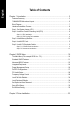
English Table of Contents Chapter 1 Introduction ................................................................................................. 5 Features Summary ................................................................................................................. 5 7VM400M-RZ Motherboard Layout ........................................................................................ 6 Block Diagram ..............................................................................................
Features Summary CPU Chipset Memory Slots On-Board IDE On-Board Floppy On-Board Peripherals On-Board VGA On-Board LAN On-Board Sound BIOS I/O Control Hardware Monitor Additional Features Overclocking Form Factor y y y y y y y y y y y y y y y y y y y y y y y y y y y y y y y y y y y y y y y Socket A for AMD Sempron ™ / Athlon™ XP / Athlon™ / Duron™ processor 200/266/333MHz FSB Supports 1.
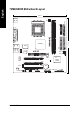
22.3 cm KB_MS LPT COMA ATX FDD CPU_FAN IDE1 AGP 8X SYS_FAN AGP VT6103 PCI1 PCI2 CD_IN PCI3 CODEC SUR_CEN 7VM400M-RZ Motherboard COMB -6- CLR_CMOS VIA VT8235 / VT8237R BAT F_USB1 F_USB2 PWR_LED GAME SPDIF JP1 DDR2 BIOS DDR1 F_AUDIO F_PANEL IDE2 LAN LINE_IN MIC_IN USB VIA KM400 IT8705 24.
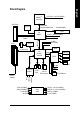
AMD-K7TM Host CPU AGP 4X/8X System Bus 200/266/333MHz FSB VGA Port VIA KM400 200/266/333MHz DDR HCLK+/- (100/133/166MHz) NBGCLK66 MHz VT6103 66MHz V_Link RJ45 AGPCLK 66MHz 3 PCI CPUCLK+/- (100/133/166MHz) 48 MHz 33 MHz 14.318 MHz BIOS PCI BUS 33MHz VIA VT8235 / VT8237R Game Port LPC BUS Floppy IT8705 AC97 Link LPT Port 24 MHz PCICLK (33MHz) USBCLK (48MHz) 14.
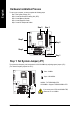
English Hardware Installation Process To set up your computer, you must complete the following steps: Step 1- Set System Jumper (JP1) Step 2- Install the Central Processing Unit (CPU) Step 3- Install Memory Modules Step 4- Install Expansion Cards Step 5- Install I/O Peripherals Cables Step 3 Step 2 Step 5 Step 5 Step 4 Step 1 Step 1: Set System Jumper (JP1) The system bus frequency can be switched at 100/133/166MHz by adjusting system jumper (JP1). (The internal frequency depend on CPU.
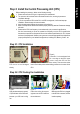
Before installing the processor, adhere to the following warning: 1. Please make sure the CPU type is supported by the motherboard. 2. The processor will overheat without the heatsink and/or fan, resulting in permanent irreparable damage. 3. If you do not match the CPU socket Pin 1 and CPU cut edge well, it will cause improper installation. Please change the insert orientation. 4. Apply thermal grease between the processor and cooling fan. 5.
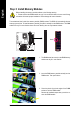
English Step 3: Install Memory Modules Before installing the memory modules, adhere to the following warning: 1. Please note that the DIMM module can only fit in one direction due to the one notch. Wrong orientation will cause improper installation. Please change the insert orientation. The motherboard has 2 dual inline memory module (DIMM) sockets. The BIOS will automatically detects memory type and size. To install the memory module, just push it vertically into the DIMM socket.
AGP 4X/8X notch 3. Please carefully pull out the small white-drawable bar at the end of the AGP slot when you try to install/ uninstall the AGP card. Please align the AGP card to the onboard AGP slot and press firmly down on the slot. Make sure your AGP card is locked by the small white-drawable bar. Step 5: Install I/O Peripherals Cables Step 5-1: I/O Back Panel Introduction X \ Y [ Z ^ _ ] ` X PS/2 Keyboard and PS/2 Mouse connector This connector supports standard PS/2 keyboard and PS/2 mouse.
English _ Line Out jack Connect the stereo speakers or earphone to this connector. ` MIC In jack Microphone can be connect to MIC In jack. After installation of the audio driver, you are able to use 2/4/6-channel audio feature by software selection. You can connect "Front speaker" to "Line Out" jack, Connect "Rear speaker" to "Line In" jack and connect "Center/Subwoofer" to "MIC In" jack.
AC power cord should only be connected to your power supply unit after ATX power cable and other related devices are firmly connected to the mainboard. 11 20 1 Pin No. Definition Pin No. Definition 1 2 3.3V 3.3V 11 12 3.
English 4) FDD (Floppy Connector) Please connect the floppy drive ribbon cables to FDD. It supports 360K, 1.2M, 720K, 1.44M and 2.88M bytes floppy disk types. The red stripe of the ribbon cable must be the same side with the Pin1. 34 33 2 1 5) IDE1 / IDE2 (IDE1 / IDE2 Connector) Please connect first hard disk to IDE1 and connect CD-ROM to IDE2. The red stripe of the ribbon cable must be the same side with the Pin1.
Please connect the power LED, PC speaker, reset switch and power switch etc. of your chassis front panel to the F_PANEL connector according to the pin assignment below.
English 9) SUR_CEN (Surround Center Connector) Please contact your nearest dealer for optional SUR_CEN cable. 1 2 5 6 Pin No. Definition 1 2 SUR OUTL SUR OUTR 3 4 GND No Pin 5 6 CENTER_OUT BASS_OUT 10) SPDIF (SPDIF Out Connector) The SPDIF output is capable of providing digital audio to external speakers or compressed AC3 data to an external Dolby Digital Decoder. Use this feature only when your stereo system has digital input function. Be careful with the polarity of the SPDIF connector.
Be careful with the polarity of the COMB connector. Check the pin assignment carefully while you connect the COMB cable, incorrect connection between the cable and connector will make the device unable to work or even damage it. For optional COMB cable, please contact your local dealer. Pin No.
English 15) CLR_CMOS (Clear CMOS) You may clear the CMOS data to its default values by this jumper. To clear CMOS, temporarily short 1-2 pin. Default doesn't include the "Shunter" to prevent from improper use this jumper. Close: Clear CMOS 1 Open: Normal 1 16) BAT (Battery) CAUTION Danger of explosion if battery is incorrectly replaced. Replace only with the same or equivalent type recommended by the manufacturer. Dispose of used batteries according to the manufacturer's instructions.
BIOS Setup is an overview of the BIOS Setup Program. The program that allows users to modify the basic system configuration. This type of information is stored in battery-backed CMOS RAM so that it retains the Setup information when the power is turned off. ENTERING SETUP Powering ON the computer and pressing immediately will allow you to enter Setup. If you require more advanced BIOS settings, please go to "Advanced BIOS" setting menu.
English If you can't find the setting you want, please press "Ctrl+F1" to search the advanced option hidden. • Standard CMOS Features This setup page includes all the items in standard compatible BIOS. • Advanced BIOS Features This setup page includes all the items of Award special enhanced features. • Integrated Peripherals This setup page includes all onboard peripherals. • Power Management Setup This setup page includes all the items of Green function features.
CMOS Setup Utility-Copyright (C) 1984-2004 Award Software Standard CMOS Features ` ` ` ` Date (mm:dd:yy) Time (hh:mm:ss) Tue, Nov 2 2004 22:31:24 IDE IDE IDE IDE [None] [None] [None] [None] Primary Master Primary Slave Secondary Master Secondary Slave Drive A Drive B Floppy 3 Mode Suport [1.44M, 3.
English Drive A / Drive B The category identifies the types of floppy disk drive A or drive B that has been installed in the computer. None No floppy drive installed 360K, 5.25" 5.25 inch PC-type standard drive; 360K byte capacity. 1.2M, 5.25" 5.25 inch AT-type high-density drive; 1.2M byte capacity (3.5 inch when 3 Mode is Enabled). 720K, 3.5" 3.5 inch double-sided drive; 720K byte capacity 1.44M, 3.5" 3.5 inch double-sided drive; 1.44M byte capacity. 2.88M, 3.5" 3.5 inch double-sided drive; 2.
CMOS Setup Utility-Copyright (C) 1984-2004 Award Software Advanced BIOS Features First Boot Device Second Boot Device Third Boot Device Password Check [Floppy] [HDD-0] [CDROM] [Setup] Item Help Menu Level` Select Boot Device priority [Floppy] Boot from floppy [LS120] Boot from LS120 [HDD-0] Boot from First HDD [HDD-1] Boot from Second HDD KLJI: Move Enter: Select F5: Previous Values +/-/PU/PD: Value F10: Save F6: Fail-Safe Defaults ESC: Exit F1: General Help F7: Optimized Defaults First / Second / Thi
English Integrated Peripherals CMOS Setup Utility-Copyright (C) 1984-2004 Award Software Integrated Peripherals OnChip IDE Channel0 OnChip IDE Channel1 AC97 Audio VIA Onboard LAN USB 1.1 Controller USB 2.
Enabled Disabled English USB Mouse Support Enable USB mouse support. Disable USB mouse support. (Default value) On-Chip LAN Boot ROM This function decide whether to invoke the boot ROM of the onboard LAN chip. Disabled Disable this function. (Default Value) Enabled Enable this function. Onboard Serial Port 1 Auto 3F8/IRQ4 2F8/IRQ3 3E8/IRQ4 2E8/IRQ3 Disabled BIOS will automatically setup the port 1 address. Enable onboard Serial port 1 and address is 3F8.
English Power Management Setup CMOS Setup Utility-Copyright (C) 1984-2004 Award Software Power Management Setup ACPI Suspend Type x USB Device Wake-Up from S3 Power LED in S1 state Soft-Off by PWRBTN AC BACK Function Keyboard Power On Mouse Power On PME Event Wake Up ModemRingOn/WakeOnLan Resume by Alarm x Date (of Month) Alarm x Time (hh:mm:ss) Alarm KLJI: Move Enter: Select F5: Previous Values [S1(POS)] Disabled [Blinking] [Instant-Off] [Soft-Off] [Disabled] [Disabled] [Enabled] [Enabled] [Disabled] Ev
When set at Enabled, any PCI-PM event can awake the system from a PCI-PM controlled stated. This feature requires an ATX power supply that provides at least 1A on the +5VSB lead. Disabled Disable this function. Enabled Enable PME as wake up event. (Default value) ModemRingOn/WakeOnLan An incoming call via modem or an input signal comes from the other client server on the LAN can awake the system from any suspend state. Disabled Disable Modem Ring on function. Enabled Enable Modem Ring on function.
English PC Health Status CMOS Setup Utility-Copyright (C) 1984-2004 Award Software PC Health Status Vcore 25VSTR +3.3V +12V Current System Temperature Current CPU Temperature Current CPU FAN Speed Current SYSTEM FAN Speed CPU FAN Fail Warning SYSTEM FAN Fail Warning KLJI: Move Enter: Select F5: Previous Values OK OK OK OK 32 oC 45 oC 4687 RPM 0 RPM [Disabled] [Disabled] +/-/PU/PD: Value F10: Save F6: Fail-Safe Defaults Current Voltage (V) Vcore / 25VSTR / +3.
CMOS Setup Utility-Copyright (C) 1984-2004 Award Software Frequency/Voltage Control Auto Detect PCI/DIMM Clk Spread Specturm CPU Host Clock Control x CPU Clock DRAM Clock(MHz) AGP OverVoltage Control DIMM OverVoltage Control [Enabled] [Enabled] [Disabled] 133MHz [By SPD] [Auto] [Auto] KLJI: Move Enter: Select F5: Previous Values +/-/PU/PD: Value F10: Save F6: Fail-Safe Defaults Item Help Menu Level` ESC: Exit F1: General Help F7: Optimized Defaults Incorrect using these features may cause your system
English DIMM OverVoltage Control Increase DIMM voltage may get stable for over-clock. But it may damage to memory module when enable this feature. Auto Supply voltage as DIMM required. (Default value) +0.1V Increase DIMM voltage +0.1V. +0.2V Increase DIMM voltage +0.2V. +0.3V Increase DIMM voltage +0.3V.
English Set Supervisor/User Password CMOS Setup Utility-Copyright (C) 1984-2004 Award Software ` ` ` ` ` ` ` Standard CMOS Features Advanced BIOS Features Integrated Peripherals Power Management Setup PnP/PCI Configurations Enter Password: PC Health Status Frequency/Voltage Control Load Fail-Safe Defaults Load Optimized Defaults Set Supervisor Password Set User Password Save & Exit Setup Exit Without Saving KLJI: Select Item F10: Save & Exit Setup ESC: Quit F8: Q-Flash Change/Set/Disable Password When
English Save & Exit Setup CMOS Setup Utility-Copyright (C) 1984-2004 Award Software ` ` ` ` ` ` ` Standard CMOS Features Load Fail-Safe Defaults Advanced BIOS Features Load Optimized Defaults Integrated Peripherals Set Supervisor Password Power Management Setup Set User Password PnP/PCI Configurations Save to CMOS and EXITSave (Y/N)? & Exit Y Setup PC Health Status Exit Without Saving Frequency/Voltage Control KLJI: Select Item F10: Save & Exit Setup ESC: Quit F8: Q-Flash Save & Exit Setup Type "Y" wil
English Revision Chapter History 3 Install Drivers Install Drivers Pictures below are shown in Windows XP Insert the driver CD-title that came with your motherboard into your CD-ROM drive, the driver CD-title will auto start and show the installation guide. If not, please double click the CD-ROM device icon in "My computer", and execute the setup.exe. Install Chipset Drivers This page shows the drivers that need to be installed for the system.
English Driver install finished ! You have to reboot system ! Item Description VIA 4IN1 Driver For INF, AGP, IDE and DMA driver. VIA KM400 VGA Driver For KM400 drvier. USB Patch for WinXP This patch driver can help you to resolve the USB device wake up S3 hang up issue in XP. VIA Lan Driver For VIA Phy family Lan driver. VIA AC97 Audio Driver Audio driver for VIA codec chipset. VIA USB 2.0 Controller For VIA VT8233 (VT6203) / VIA VT8235 / VIA VT8237 / VIA VT8237R south bridge. For USB2.
Taiwan (Headquarters) GIGA-BYTE TECHNOLOGY CO., LTD. Address: No.6, Bau Chiang Road, Hsin-Tien, Taipei Hsien, Taiwan. TEL: +886 (2) 8912-4888 FAX: +886 (2) 8912-4003 Tech. Support : http://tw.giga-byte.com/TechSupport/ServiceCenter.htm Non-Tech. Support(Sales/Marketing) : http://ggts.gigabyte.com.tw/nontech.asp WEB address (English): http://www.gigabyte.com.tw WEB address (Chinese): http://chinese.giga-byte.com U.S.A. G.B.T. INC. Address: 17358 Railroad St, City of Industry, CA 91748.
English China NINGBO G.B.T. TECH. TRADING CO., LTD. Tech. Support : http://cn.giga-byte.com/TechSupport/ServiceCenter.htm Non-Tech. Support(Sales/Marketing) : http://ggts.gigabyte.com.tw/nontech.asp WEB address : http://www.gigabyte.com.