7VT600-RZ / 7VT600-RZ-C AMD Athlon™ / Athlon™ XP / Duron™ Socket A Processor Motherboard User's Manual Rev. 1003 12ME-7VT600RZ-1003 Copyright © 2004GIGABYTE TECHNOLOGYCO., LTD Copyright by GIGA-BYTETECHNOLOGY CO.,LTD. ("GBT"). No part of this manual may be reproduced or transmitted in any from without the expressed, written permission of GBT. Trademarks Third-party brands and names are the propertyof their respective owners.
Mother Board 7VT600-RZ Feb. 20, 2004 Motherboard 7VT600-RZ Feb.
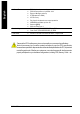
Preparing Your Computer Computer motherboards and expansion cards contain very delicate Integrated Circuit (IC) chips. To protect them against damage from static electricity, you should follow some precautions whenever you work on your computer. 1. Unplug your computer when working on the inside. 2. Use a grounded wrist strap before handling computer components. If you do not have one, touch both of your hands to a safely grounded object or to a metal object, such as the power supply case. 3.
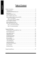
English Table of Content Chapter 1 Introduction ................................................................................................ 5 Features Summary ..............................................................................................................................5 7VT600-RZ Series Motherboard Layout..............................................................................................7 Block Diagram ..........................................................................
Features Summary CPU Chipset Memory Slots On-Board IDE On-Board Floppy On-Board Peripherals On-Board LAN * On-Board Sound On-Board USB 2.0 BIOS I/O Control Hardware M onitor — — — — — — — — — — — — — — — — — — — — — — — — — — — — — — — — — — Socket A processor TM TM TM AMD Athlon / Athlon XP/ Duron (K7) 128K L1 & 512K/256K/64K L2 cache on die 200/266/333/400 MHz FSB Supports 1.
English Additional Features Overclocking Form Factor — — — — — — — — — — — PS/2 Keyboard power on by password, PS/2 M ouse power on by double click Exter n al M odem wake up STR(Suspend-To-RAM) AC Recovery Poly fuse for keyboard over-current protection USB KB/M ouse wake up from S3 Supports @BIOS Supports EasyTune 4 Over Voltage (CPU/AGP/DDR/PCI) by BIOS Over Clock (CPU/AGP/DDR/PCI) by BIOS — 30.5cm x 20.0cm ATX size form factor, 4 layers PCB.
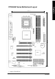
English 7VT600-RZ Series Motherboard Layout 20.0 cm CPU_FAN KB_MS ATX LAN * USB COMB 7VT600-RZ LPT COMA SOCKET A FDD VIA KT600 CLR_CMOS 30.5 cm DDR3 DDR1 AGP DDR2 CD_IN F_AUDIO AUDIO PCI1 V T6103L* BATTERY JP1 PCI2 PCI3 CODEC V T8 235 SYS_FAN PCI4 SUR_CEN PCI5 -C IDE2 I T8 705 IDE1 BIOS GAME CI AUX_IN SPDI F_IO F_PANEL F_U SB1 F_U SB2 PWR_LED " * " Support 7VT600-RZ only.
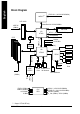
AMD-K7TM CPUCLK+/- (100/133/166/200MHz) AGP 4X/8X System Bus100/133/166/200MHz AGPCLK (66MHz) VIA KT600 DDR RAM HCLK+/- (100/133/166/200MHz) RJ45* VIA VT6103L* 66MHz V_Link GCLK(66MHz) 5 PCI 48 MHz 33 MHz 14.318 MHz VCLK(66MHz) BIOS VIA VT8235 Game Port AC97 Link IT8705 33 MHz PCICLK (33MHz) USBCLK (48MHz) 14.
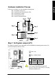
English Hardware Installation Process To set up your computer, you must complete the following steps: Step 1- Set System Jum per (JP1) Step 2- Install the Central Processing Unit (CPU) Step 3- Install memory modules Step 4- Install expansion cards Step 5- Install I/O Peripherals cables Step 2 Step 3 Step 5 Step 5 Step 1 Step 4 Step 5 Step 1: Set System Jumper (JP1) The system bus frequency can be switched at 100/133/166/200M Hz by adjusting system jumper (JP1). (The internal frequency depend on CPU.
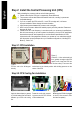
English Step 2: Install the Central Processing Unit (CPU) Before installing the processor, adhere to the following warning: 1. Please make sure the CPU type is supported by the motherboard. 2. The processor will overheat without the heatsink and/or fan, resulting in permanent irreparable damage. 3. If you do not match the CPU socket Pin 1 and CPU cut edge well, it will cause improper installation. Please change the insert orientation. 4. Apply therm al grease between the processor and cooling fan. 5.
Before installing the mem ory modules, adhere to the following warning: 1. When DIMM LED is ON, do not install / remove DIMM from socket. 2. Please note that the DIMM module can only fit in one direction due to the one notch. Wrong orientation will cause improper installation. Please change the insert orientation. The motherboard has 3 dual inline mem ory module (DIMM) sockets. The BIOS will automatically detects mem ory type and size.
English Step 4: Install Expansion Cards 1. Read the related expansion card's instruction document before install the expansion card into the com puter. 2. Please m ake sure your AGP card is AGP 4X/8X (1.5V). AGP 4X /8X notch 3. Please carefully pull out the small white- drawable bar at the end of the AGP slot when you try to install/ Uninstall the AGP card. Please align the AGP card to the onboard AGP slot and press firmly down on the slot .
Step 5-2 : Connectors Introduction 1 3 5 9 17 8 11 2 10 4 15 12 13 16 6 7 14 1) CPU_FAN 2) SYS_FAN 10) SUR_CEN 11) CD_IN 3) 4) 5) 6) 12) 13) 14) 15) ATX (ATX Power) IDE1 / IDE2 FDD PWR_LED 7) F_PANEL 8) BATTERY 9) F_AUDIO AUX_IN SPDIF_IO F_USB1 / F_USB2 GAME 16) CI (Case Open) 17) CLR_CMOS - 13 - Hardware Installation Process English { Line In jack Devices like CD-ROM, walkman etc. can be connect to Line In jack.
English 1) CPU_FAN (CPU FAN Connector) Please note, a proper installation of the CPU cooler is essential to prevent the CPU from running under abnormal condition or damaged by overheating.The CPU fan connector supports Max. current up to 600 mA. Pin No. 1 2 3 1 Definition GND +12V Sense 2) SYS_FAN (System FAN Connector) This connector allows you to link with the cooling fan on the system case to lower the system temperature. Pin No.
Please connect first harddisk to IDE1 and connect CDROM to IDE2. The red stripe of the ribbon cable must be the same side with the Pin1. 1 39 2 40 IDE2 IDE1 5) FDD (Floppy Connector) Please connect the floppy drive ribbon cables to FDD. It supports 360K,720K,1.2M,1.44M and 2.88Mbytes floppy disk types. The red stripe of the ribbon cable m ust be the same side with the Pin1. 34 2 33 1 6) PWR_LED PWR_LED is connect with the system power indicator to indicate whether the system is on/off.
Please connect the power LED, PC speaker, reset switch and power switch etc. of your chassis front panel to the F_PANEL connector according to the pin assignm ent below.
If you want to use Front Audio connector, you must remove 5-6, 9-10 Jumper. In order to utilize the front audio header, your chassis must have front audio connector. Also please make sure the pin assigment on the cable is the same as the pin assigment on the MB header. To find out if the chassis you are buying support front audio connector, please contact your dealer. Please note, you can have the alternative of using front audio connector or of using rear audio connector to play sound.
English 12) AUX_IN ( AUX In Connector) Connect other device (such as PCI TV Tunner audio out)to the connector. 1 Pin No. 1 2 3 4 Definition AUX-L GND GND AUX-R 13) SPDIF_IO (SPDIF In/Out Connector) The SPDIF output is capable of providing digital audio to external speakers or compressed AC3 data to an external Dolby Digital Decoder. Use this feature only when your stereo system has digital input and output function. Use SPDIF in feature only when your device has digital output function.
Be careful with the polarity of the F_USB connector. Check the pin assignment carefully while you connect the F_USB cable, incorrect connection between the cable and connector will make the device unable to work or even damage it. For optional F_USB cable, please contact your local dealer. 2 10 1 9 Pin No.
English 17) CLR_CMOS (Clear CMOS) You may clear the CMOS data to its default values by this jumper. To clear CMOS, temporarily shor 1-2 pin. Default doesn't include the "Shunter" to prevent from improper use this jumper.
BIOS Setup is an overview of the BIOS Setup Program. The program that allows users to modify the basic system configuration. This type of inform ation is stored in battery-backed CMOS RAM so that it retains the Setup information when the power is turned off. ENTERING SETUP Powering ON the com puter and pressing immediately will allow you to enter Setup. If you require m o re adv anc ed BIO S s ettin gs, pl eas e g o to " Adv anc ed BIO S" se tti ng m en u.
English If you can't find the setting you want, please press "Ctrl+F1" to search the advanced option hidden. • Standard CMOS Features This setup page includes all the item s in standard com patible BIOS. • Advanced BIOS Features This setup page includes all the items of Award special enhanced features. • Integrated Peripherals This setup page includes all onboard peripherals. • Power Management Setup This setup page includes all the items of Green function features.
CMOS Setup Utility-Copyright (C) 1984-2004 Award Software Standard CMOS Features } } } } Date (mm:dd:yy) Time (hh:mm:ss) Fri, Jan 9 2004 22:31:24 IDE IDE IDE IDE [None] [None] [None] [None] Primary Master Primary Slave Secondary Master Secondary Slave Drive A Drive B Floppy 3 Mode Suport [1.44M, 3.
English F Drive A / Drive B The category identifies the types of floppy disk drive A or drive B that has been installed in the computer. 8None 8360K, 5.25 “. 81.2M, 5.25 ”. 8720K, 3.5 “. 81.44M, 3.5 “. 82.88M, 3.5 “. No floppy drive installed 5.25 inch PC-type standard drive; 360K byte capacity. 5.25 inch AT-type high-density drive; 1.2M byte capacity (3.5 inch when 3 Mode is Enabled). 3.5 inch double-sided drive; 720K byte capacity 3.5 inch double-sided drive; 1.44M byte capacity. 3.
CMOS Setup Utility-Copyright (C) 1984-2004 Award Software Advanced BIOS Features First Boot Device Second Boot Device Third Boot Device [Floppy] [HDD-0] [CDROM] Password Check [Setup] Item Help Menu Level} Select Boot Device priority [Floppy] Boot from floppy [LS120] Boot from LS120 [HDD-0] Boot from First HDD [HDD-1] Boot from Second HDD higf : Move Enter: Select F5: Previous Values +/-/PU/PD: Value F10: Save F6: Fail-Save Default ESC: Exit F1: General Help F7: Optimized Defaults F First / Second /
English Integrated Peripherals CMOS Setup Utility-Copyright (C) 1984-2003 Award Software Integrated Peripherals OnChip IDE Channel0 OnChip IDE Channel1 AC97 Audio VIA Onboard LAN * USB 1.1 Controller USB 2.
8Enabled 8Disabled English F USB Keyboard Support MWhen a USB keyboard is installed, please set at Enabled. Enabled USB Keyboard Support. Disabled USB Keyboard Support. (Default value) F USB Mouse Support 8Enabled 8Disabled Enabled USB M ouse Support. Disabled USB Mouse Support. (Default value) F VIA LAN Boot ROM * This function decide whether to invoke the boot ROM of the onboard LAN chip. 8Disabled Disable this function. (Default Value) 8Enabled Enable this function.
English F Parallel Port Mode M This feature allows you to connect with an advanced print via the port mode it supports. 8SPP 8EPP 8ECP 8ECP+EPP Using Parallel port as Standard Parallel Port using IRQ7. (Default Value) Using Parallel port as Enhanced Parallel Port IRQ5. Using Parallel port as Extended Capabilities Port using IRQ7. Using Parallel port as ECP & EPP mode. F Game Port Address 8Disabled 8201 8209 Disabled this function. Set Gam e Port Address to 201.
8S1(POS) 8S3(STR) Set suspend type to Power On Suspend under ACPI OS(Power On Suspend). (Default value) Set suspend type to Suspend To RAM under ACPI OS (Suspend To RAM). F USB Device Wakeup From S3(When ACPI Suspend Type is set [S3(STR)]) USB device wakeup From S3 can be set when ACPI standby state set to S3/STR. 8Enabled USB Device can wakeup system from S3. 8Disabled USB Device can’t wakeup system from S3.
English F ModemRingOn/WakeOnLAN (When AC Back Function set to [Soft-Off]) You can enable wake on LAN feature by the "ModemRingOn/WakeOnLAN" or "PME Event Wake up" when the M /B has "WOL" onboard connector. Only enabled the feature by "PME Event Wake up". An incoming call via modem awakes the system from its soft-off m ode. When set at Enabled, an input signal comes from the other client. Server on the LAN awaks the system from a soft off state if connected over LAN.
8Auto 83,4,5,7,9.,10,11,12,14,15 English F PCI1/PCI5 IRQ Assignment Auto assign IRQ to PCI 1/ PCI 5. (Default value) Set 3,4,5,7,9,10,11,12,14,15 to PCI1/ PCI5. F PCI2 IRQ Assignment 8Auto 83,4,5,7,9.,10,11,12,14,15 Auto assign IRQ to PCI 2. (Default value) Set 3,4,5,7,9,10,11,12,14,15 to PCI2. F PCI3 IRQ Assignment 8Auto 83,4,5,7,9.,10,11,12,14,15 Auto assign IRQ to PCI 3. (Default value) Set 3,4,5,7,9,10,11,12,14,15 to PCI3. F PCI4 IRQ Assignment 8Auto 83,4,5,7,9.
English F Reset Case Open Status F Case Opened If the case is closed, "Case Opened" will show "No". If the case have been opened, "Case Opened" will show "Yes". If you want to reset "Case Opened" value, set "Reset Case Open Status" to "Enabled" and save CM OS, your computer will restart. F Current Voltage (V) Vcore / DDR Vtt / +3.3V/ +5V / +12V / 5VSB Detect system 's voltage status autom atically. F Current System Temperature (°C) Detect System Tem p. automatically.
8Disabled 8Enabled English FSpread Spectrum Modulated Disable clock spread spectrum. Enable clock spread spectrum.(Default value) F CPU Host Clock Control Note: If system hangs up before enter CMOS setup utility, wait for 20 sec for times out reboot . When tim e out occur, system will reset and run at CPU default Host clock at next boot. 8Disable Disable CPU Host Clock Control.(Default value) 8Enable Enable CPU Host Clock Control.
English Load Fail-Safe Defaults CMOS Setup Utility-Copyright (C) 1984-2004 Award Software } Standard CMOS Features Load Fail-Safe Defaults } Advanced BIOS Features Load Optimized Defaults } Integrated Peripherals Set Supervisor Password } } Power Management Setup PnP/PCI Configurations Set User Password Load Fail-Safe Defaults Save (Y/N)? & Exit N Setup } PC Health Status } Frequency/Voltage Control Exit Without Saving higf : Select Item ESC: Quit F8: Q-Flash F10: Save & Exit Setup Load
English Set Supervisor/User Password CMOS Setup Utility-Copyright (C) 1984-2004 Award Software } Standard CMOS Features Load Fail-Safe Defaults } Advanced BIOS Features Load Optimized Defaults } Integrated Peripherals Set Supervisor Password } } Power Management Setup PnP/PCI Configurations Enter Password: Set User Password Save & Exit Setup } PC Health Status Exit Without Saving } Frequency/Voltage Control higf : Select Item ESC: Quit F8: Q-Flash F10: Save & Exit Setup Change/Set/Disable
English Save & Exit Setup CMOS Setup Utility-Copyright (C) 1984-2004 Award Software } Standard CMOS Features Load Fail-Safe Defaults } Advanced BIOS Features Load Optimized Defaults } Integrated Peripherals Set Supervisor Password } } Power Management Setup PnP/PCI Configurations } PC Health Status } Frequency/Voltage Control Set User Password Save to CMOS and EXITSave (Y/N)? & Exit Y Setup Exit Without Saving higf : Select Item ESC: Quit F8: Q-Flash F10: Save & Exit Setup Save Data to CM
English Revision ChapterHistory 3 Install Drivers Install Drivers Picture below are shown in Windows XP Insert the driver CD-title that came with your motherboard into your CD-ROM drive, the driver CD-title will auto start and show the installation guide. If not, please double click the CD-ROM device icon in "My com puter", and execute the setup.exe. INSTALL CHIPSET DRIVER This page shows the drivers that need to be installed for the system.
English Driver install finished ! You have to reboot system ! Item Description n VIA 4IN1 Driver For INF, AGP, IDE and DM A Driver n USB Path for WinXP This patch driver can help you to resolve the USB device wake up S3 hang up issue in XP n VIA Lan Driver * VIA 10/100 LAN driver for VT6103L chips n RealTek AC97 Audio Driver Audio driver for Realtek AC97 codec chipset n VIA USB 2.0 Controller USB 2.0 Driver information for XP For USB2.
English - 39 - Driver Installation
English CONTACT US Contact us via the information in this page all over the world. — Taiwan Gigabyte TechnologyCo., Ltd. Address: No.6, Bau Chiang Road, Hsin-Tien, Taipei Hsien, Taiwan,R.O.C. Tel: 886 (2) 8912-4888 Fax: 886 (2) 8912-4004 Tech.Support: http://tw.giga-byte.com/TechSupport/ServiceCenter.htm Non-Tech.Support (Sales/Marketing issues): http://ggts.gigabyte.com.tw/nontech.asp Website: http://www.gigabyte.com.tw — USA G.B.T. INC. Address: 17358 Railroad St, City of Industry, CA 91748.