
Technology Computer Hardware User Manual

- 15 - Hardware Installation Process
English
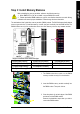
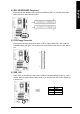
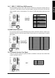
4) IDE1/ IDE2(IDE1/IDE2 Connector)
Please connect first harddisk to IDE1 and connect CDROM to IDE2. The red stripe of the ribbon
cable must be the same side with the Pin1.
IDE1
IDE2
2
4 0
1
3 9
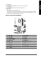
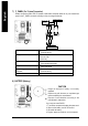
5) FDD (Floppy Connector)
Please connect the floppy drive ribbon cables to FDD. It supports 360K,720K,1.2M,1.44M and
2.88Mbytes floppy disk types. The red stripe of the ribbon cable m ust be the same side with the
Pin1.
1
3 4
2
3 3
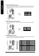
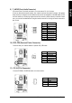
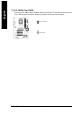
6) PWR_LED
PWR_LED is connect with the system power indicator to indicate whether the system is on/off. It
will blink when the system enters suspend mode. If you use dual color LED, power LED will turn
to another color.
1
Pin No. Definition
1 MPD+
2 MPD-
3 MPD-