8S648FX-RZ / 8S648FX-RZ-C Intel® Pentium® 4 Processor Motherboard User's Manual Rev. 1002 12ME-S648FXRZ-1002 Copyright © 2003 GIGABYTE TECHNOLOGY CO., LTD Copyright by GIGA-BYTE TECHNOLOGY CO., LTD. ("GBT"). No part of this manual may be reproduced or transmitted in any from without the expressed, written permission of GBT. Trademarks Third-party brands and names are the property of their respective owners.
Mother Board 8S648FX-RZ Mar. 20, 2004 Motherboard 8S648FX-RZ Mar.
Preparing Your Computer Computer motherboards and expansion cards contain very delicate Integrated Circuit (IC) chips. To protect them against damage from static electricity, you should follow some precautions whenever you work on your computer. 1. Unplug your computer when working on the inside. 2. Use a grounded wrist strap before handling computer components. If you do not have one, touch both of your hands to a safely grounded object or to a metal object, such as the power supply case. 3.
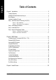
English Table of Contents Chapter 1 Introduction ................................................................................................... 5 Features Summary .................................................................................................................. 5 8S648FX-RZ Series Motherboard Layout .................................................................................. 6 Block Diagram ..........................................................................................
Features Summary CPU Chipset Memory Slots On-Board IDE On-Board Floppy On-Board Peripherals On-Board LAN * On-Board Sound BIOS I/O Control Hardware Monitor Additional Features Overclocking Form Factor y y y y y y y y y y y y y y y y y y y y y y y y y y y y y y y y y y y y y y y y Socket 478 for Intel® Pentium® 4 (Northwood, Prescott) with HT Technology Intel ® Pentium ® 4 800/533/400MHz FSB 2nd cache depends on CPU North Bridge: SiS 648FX South Bridge: SiS 963L 3 184-pin DDR DIMM sockets, supports u
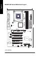
CPU_FAN 21 cm SOCKET478 F_AUDIO DDR2 AGP 8X AGP IDE1 DDR3 * DDR1 SiS 648FX USB_LAN * 29.5 cm 8S648FX-RZ ATX_12V ICS 1883 ATX IDE2 GAME MIC_IN LINE_OUT LINE_IN COMB LPT Hyper Threading Support COMA KB_MS CLR_CMOS CODEC PCI1 CD_IN PCI2 SUR_CEN VRM10.0 AUX_IN PCI3 IT8705 -C # English 8S648FX-RZ Series Motherboard Layout BIOS SiS 963L BAT PCI4 P4 Titan PCI5 SPDIF_IO FDD F_USB2 SYS _FAN F_USB1 F_PANEL PWR_LED "*" Only for 8S648FX-RZ. "#" Only for 8S648FX-RZ-C.
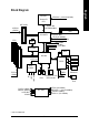
Pentium 4 Socket 478 CPU AGP 4X/8X CPUCLK+/- (100/133/200 MHz) System Bus 400/533/800 MHz AGPCLK (66MHz) DDR SiS 648FX 5 PCI 266/333/400 MHz ZCLK (66/133MHz) HCLK+/- (100/133MHz) RJ45 * 66/133 MHz 33 MHz 14.318 MHz 48 MHz ICS 1883 * BIOS SiS 963L AC97 Link Game Port LPC BUS IT8705 Floppy LPT Port AC97 CODEC PCICLK (33MHz) MIC PCICLK (33MHz) USBCLK (48MHz) 14.
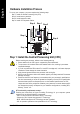
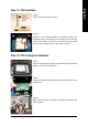
Step 4 Step 1 Step 2 Step 4 Step 4 Step 3 -C English Hardware Installation Process To set up your computer, you must complete the following steps: Step 1- Install the Central Processing Unit (CPU) Step 2- Install memory modules Step 3- Install expansion cards Step 4- Install I/O Peripherals Cables Step 1: Install the Central Processing Unit (CPU) Before installing the processor, adhere to the following warning: 1. Please make sure the CPU type is supported by the motherboard. 2.
Socket Actuation Lever English Step 1-1: CPU Installation Figure 1. Pull the rod to the 90-degree directly. Figure 2. Locate Pin 1 in the socket and look for a (golden) cut edge on the CPU upper corner. Insert the CPU into the socket. (Do not force the CPU into the socket.) Then move the socket lever to the locked position while holding pressure on the center of the CPU. Step 1-2: CPU Cooling Fan Installation Figure 1.
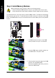
Before installing the memory modules, adhere to the following warning: 1. Please note that the DIMM module can only fit in one direction due to the one notch. Wrong orientation will cause improper installation. Please change the insert orientation. The motherboard has 3 dual inline memory module (DIMM) sockets. The BIOS will automatically detects memory type and size. To install the memory module, just push it vertically into the DIMM socket. The DIMM module can only fit in one direction due to the notch.
AGP 4X/8X notch 3. Please carefully pull out the small white- drawable bar at the end of the AGP slot when you try to install/ Uninstall the AGP card. Please align the AGP card to the onboard AGP slot and press firmly down on the slot .Make sure your AGP card is locked by the small white- drawable bar.
Microphone can be connect to MIC In jack. After installation of the audio driver, you are able to use 2/4/6-channel audio feature by software selection. You can connect "Front speaker" to "Line Out" jack, Connect "Rear speaker" to "Line In" jack and connect "Center/Subwoofer" to "MIC In" jack. LAN port * ` LAN is fast Ethernet with 10/100Mbps speed. USB port a Before you connect your device(s) into USB connector(s), please make sure your device(s) such as USB keyboard, mouse, scanner, zip, speaker...
English 1) ATX_12V (+12V Power Connector) This connector (ATX_12V) supplies the CPU operation voltage (Vcore). If this "ATX_12V connector" is not connected, system cannot boot. Pin No. 4 3 1 GND GND 3 4 +12V +12V -C 2 Definition 1 2 2) ATX (ATX Power) AC power cord should only be connected to your power supply unit after ATX power cable and other related devices are firmly connected to the mainboard. 10 Pin No. 20 -C 11 1 Definition Pin No. Definition 1 2 3.3V 3.3V 11 12 3.
This connector allows you to link with the cooling fan on the system case to lower the system temperature. Pin No. Definition 1 2 GND +12V 3 Sense -C 1 5) IDE1 / IDE2 (IDE1 / IDE2 Connector) Important Notice: Please connect first hard disk to IDE1 and connect CD-ROM to IDE2. The red stripe of the ribbon cable must be the same side with the Pin1. 40 IDE2 -C 2 39 IDE1 1 6) FDD (Floppy Connector) Please connect the floppy drive ribbon cables to FDD. It supports 360K, 1.2M, 720K, 1.44M and 2.
PWR_LED is connect with the system power indicator to indicate whether the system is on/off. It will blink when the system enters suspend mode. If you use dual color LED, power LED will turn to another color. Pin No. 1 1 Definition MPD+ MPDMPD- -C 2 3 8) F_PANEL (2 x 10 pins Connector) Please connect the power LED, PC speaker, reset switch and power switch etc of your chassisfront panel to the F_PANEL connector according to the pin assignment below.
If you want to use Front Audio connector, you must remove 5-6, 9-10 Jumper. In order to utilize the front audio header, your chassis must have front audio connector. Also please make sure the pin assigment on the cable is the same as the pin assigment on the MB header. To find out if the chassis you are buying support front audio connector, please contact your dealer. Please note, you can have the alternative of using front audio connector or of using rear audio connector to play sound. Pin No.
Connect other device(such as PCI TV Tunner audio out)to the connector. Pin No. Definition 1 2 AUX-L GND 3 4 GND AUX-R -C 1 13) SPDIF_IO (SPDIF In/Out Connector) The SPDIF output is capable of providing digital audio to external speakers or compressed AC3 data to an external Dolby Digital Decoder. Use this feature only when your stereo system has digital input function. Be careful with the polarity of the SPDIF_IO connector.
Be careful with the polarity of the front USB connector. Check the pin assignment carefully while you connect the front USB cable, incorrect connection between the cable and connector will make the device unable to work or even damage it. For optional front USB cable, please contact your local dealer. Pin No.
BIOS Setup is an overview of the BIOS Setup Program. The program that allows users to modify the basic system configuration. This type of information is stored in battery-backed CMOS RAM so that it retains the Setup information when the power is turned off. ENTERING SETUP Powering ON the computer and pressing immediately will allow you to enter Setup. If you require more advanced BIOS settings, please go to "Advanced BIOS" setting menu.
English If you can't find the setting you want, please press "Ctrl+F1" to search the advanced option hidden. • Standard CMOS Features This setup page includes all the items in standard compatible BIOS. • Advanced BIOS Features This setup page includes all the items of Award special enhanced features. • Integrated Peripherals This setup page includes all onboard peripherals. • Power Management Setup This setup page includes all the items of Green function features.
CMOS Setup Utility-Copyright (C) 1984-2004 Award Software Standard CMOS Features ` ` ` ` Date (mm:dd:yy) Time (hh:mm:ss) Fri, Jan 9 2004 22:31:24 IDE IDE IDE IDE [None] [None] [None] [None] Primary Master Primary Slave Secondary Master Secondary Slave Drive A Drive B Floppy 3 Mode Suport [1.44M, 3.
English Drive A / Drive B The category identifies the types of floppy disk drive A or drive B that has been installed in the computer. None No floppy drive installed 360K, 5.25" 5.25 inch PC-type standard drive; 360K byte capacity. 1.2M, 5.25" 5.25 inch AT-type high-density drive; 1.2M byte capacity (3.5 inch when 3 Mode is Enabled). 720K, 3.5" 3.5 inch double-sided drive; 720K byte capacity 1.44M, 3.5" 3.5 inch double-sided drive; 1.44M byte capacity. 2.88M, 3.5" 3.5 inch double-sided drive; 2.
CMOS Setup Utility-Copyright (C) 1984-2004 Award Software Advanced BIOS Features First Boot Device Second Boot Device Third Boot Device Boot Up Floppy Seek Password Check CPU Hyper-Threading # Init Display First [Floppy] [HDD-0] [CDROM] [Disabled] [Setup] [Enabled] [AGP] Item Help Menu Level` Select Boot Device priority [Floppy] Boot from floppy [LS120] Boot from LS120 [HDD-0] Boot from First HDD [HDD-1] Boot from Second HDD KLJI: Move Enter: Select F5: Previous Values +/-/PU/PD: Value F10: Save F6: Fai
English CPU Hyper-Threading Enabled Disabled Enables CPU Hyper Threading Feature. Please note that this feature is only working for operating system with multi processors mode supported. (Default value) Disables CPU Hyper Threading. Init Display First Select the first initation of monitor or display from AGP or PCI VGA card. AGP Set Init display first to AGP. (Default value) PCI Set Init display first to PCI.
Enabled Disabled English AC97 Audio Enable onboard AC'97 audio function. (Default value) Disable this function. On Board LAN device * Disabled Enabled Disable this function. Enable Onboard Lan Chip device. (Default value) USB Controller Enabled Disabled Enable USB Controller. (Default value) Disable USB Controller. USB Legacy Support When USB keyboard or mouse is installed, please set at Enabled. Enabled Enable USB keyboard or mouse support. Disabled Disable USB keyboard or mouse support.
English Game Port Address 201 209 Disabled Set Game Port Address to 201. (Default value) Set Game Port Address to 209. Disable this function. Midi Port Address 300 330 Disabled Set Midi Port Address to 300. Set Midi Port Address to 330. (Default value) Disable this function. Midi Port IRQ 5 10 Set Midi Port IRQ to 5. Set Midi Port IRQ to 10.
Disabled Enabled English IRQ [3-7, 9-15], NMI Disable this function. Enable this function. (Default value) ModemRingOn Disabled Enabled Disable Modem Ring on function. Enable Modem Ring on function. (Default value) PME Event Wake Up Disabled Enabled Disable this function. Enable PME as wake up event. (Default value) Power On by Keyboard Password Disabled Any Key Enter from 1 to 8 characters to set the keyboard power on password. Disabled this function.
English PnP/PCI Configurations CMOS Setup Utility-Copyright (C) 1984-2004 Award Software PnP/PCI Configurations PCI PCI PCI PCI 4 IRQ Assignment 1/5 IRQ Assignment 2 IRQ Assignment 3 IRQ Assignment KLJI: Move Enter: Select F5: Previous Values [Auto] [Auto] [Auto] [Auto] Item Help Menu Level` +/-/PU/PD: Value F10: Save F6: Fail-Save Default ESC: Exit F1: General Help F7: Optimized Defaults PCI 4 IRQ Assignment Auto 3,4,5,7,9,10,11,12,14,15 Auto assign IRQ to PCI 4.
CMOS Setup Utility-Copyright (C) 1984-2004 Award Software PC Health Status Vcore DDR25V +3.3V +12V Current CPU Temperature Current CPU FAN Speed Current SYSTEM FAN Speed KLJI: Move Enter: Select F5: Previous Values 1.54V 2.544V 3.360V 11.92V 41°C 4440 RPM 0 RPM Item Help Menu Level` +/-/PU/PD: Value F10: Save F6: Fail-Save Default ESC: Exit F1: General Help F7: Optimized Defaults Current Voltage (V) Vcore / DDR25V / +3.3V / +12V Detect system's voltage status automatically.
English Frequency/Voltage Control CMOS Setup Utility-Copyright (C) 1984-2004 Award Software Frequency/Voltage Control x x x x CPU Clock Ratio Linear Frequency Control CPU Clock (MHz) DRAM Clock (MHz) AGP/PCI Clock Control AGP Clock (MHz) PCI Clock (MHz) AGP Voltage Control DRAM Voltage Control KLJI: Move Enter: Select F5: Previous Values [10X] [Disabled] 100 AUTO [AUTO] 66 33 [Normal] [Normal] +/-/PU/PD: Value F10: Save F6: Fail-Save Default Item Help Menu Level` ESC: Exit F1: General Help F7: Optim
English AGP Clock (MHz) Please set AGP Clock according to your requirement. Incorrect using it may cause your system broken. For power End-User use only! PCI Clock (MHz) Please set PCI Clock according to your requirement. Incorrect using it may cause your system broken. For power End-User use only! AGP Voltage Control Normal +0.1V Set AGP Voltage Control to Normal. (Default value) Set AGP Voltage Control to +0.1V. DRAM Voltage Control Normal +0.1V Set DRAM Voltage Control to Normal.
English Load Fail-Safe Defaults CMOS Setup Utility-Copyright (C) 1984-2004 Award Software ` ` ` ` ` ` ` Standard CMOS Features Top Performance Advanced BIOS Features Load Fail-Safe Defaults Integrated Peripherals Load Optimized Defaults Power Management Setup Set Supervisor Password PnP/PCI Configurations Load Fail-Safe Defaults Set(Y/N)? User Password N PC Health Status Save & Exit Setup Frequency/Voltage Control Exit Without Saving KLJI: Select Item F10: Save & Exit Setup ESC: Quit F8: Q-Flash Load Fa
English Set Supervisor/User Password CMOS Setup Utility-Copyright (C) 1984-2004 Award Software ` ` ` ` ` ` ` Standard CMOS Features Advanced BIOS Features Integrated Peripherals Power Management Setup PnP/PCI Configurations Enter Password: PC Health Status Frequency/Voltage Control Top Performance Load Fail-Safe Defaults Load Optimized Defaults Set Supervisor Password Set User Password Save & Exit Setup Exit Without Saving KLJI: Select Item F10: Save & Exit Setup ESC: Quit F8: Q-Flash Change/Set/Disabl
English Save & Exit Setup CMOS Setup Utility-Copyright (C) 1984-2004 Award Software ` ` ` ` ` ` ` Standard CMOS Features Top Performance Advanced BIOS Features Load Fail-Safe Defaults Integrated Peripherals Load Optimized Defaults Power Management Setup Set Supervisor Password PnP/PCI Configurations Save to CMOS and EXITSet (Y/N)? User YPassword PC Health Status Save & Exit Setup Frequency/Voltage Control Exit Without Saving KLJI: Select Item F10: Save & Exit Setup ESC: Quit F8: Q-Flash Save Data to CMO
English Revision Chapter History 3 Install Drivers Install Drivers Pictures below are shown in Windows XP Insert the driver CD-title that came with your motherboard into your CD-ROM drive, the driver CD-title will auto start and show the installation guide. If not, please double click the CD-ROM device icon in "My computer", and execute the setup.exe. INSTALL CHIPSET DRIVER This page shows the drivers that need to be installed for the system.
English Driver install finished!! you have to reboot system!! Item Description SIS AGP Driver Install SIS AGP Driver. USB Patch for WinXP This patch driver can help you to resolve the USB device wake up S3 hang up issue in XP. SiS PCI Lan Driver * For SiS series Lan driver. C-Media AC97 Audio Driver Install C-Media AC97 audio driver. SIS USB 2.0 Driver It is recommended that you use the Microsoft Windows update for the most updated driver for XP/2K. "*" Only for 8S648FX-RZ.
English - 37 - Memo
English 8S648FX-RZ Series Motherboard - 38 -
English - 39 - Memo
English CONTACT US Contact us via the information in this page all over the world. y Taiwan Gigabyte Technology Co., Ltd. Address: No.6, Bau Chiang Road, Hsin-Tien, Taipei Hsien, Taiwan, R.O.C. Tel: 886 (2) 8912-4888 Fax: 886 (2) 8912-4003 Tech. Support: http://tw.giga-byte.com/TechSupport/ServiceCenter.htm Non-Tech. Support (Sales/Marketing issues): http://ggts.gigabyte.com.tw/nontech.asp Website: http://www.gigabyte.com.tw y USA G.B.T. INC. Address: 17358 Railroad St, City of Industry, CA 91748.