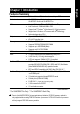
When you installing AGP card, please make sure the following notice is fully understood and practiced. If your AGP card has "AGP 4X(1.5V) notch"(show below), please make sure your AGP cardis AGP 4X(1.5V). Caution: AGP 2X(3.3V) card is not supported by Intel® 845(GE/PE) / 845(E/G) / 850(E). You might experience system unable to boot up normally. Please insert an AGP 4X(1.5V) card Example 1: Diamond Vipper V770 golden finger is compatible with 2X/4X mode AGP slot. It can be switched between AGP 2X(3.
0 The author assumes no responsibility for any errors or omissions that may appear in this document nor does the author make a commitment to update the information contained herein. 0 Third-party brands and names are the property of theirrespective owners. 0 Please do not remove any labels on motherboard, thismay void the warranty of this motherboard. 0 Due to rapid change in technology, some of the specifications might be out of date before publication of this booklet.
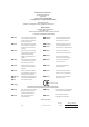
Declaration of Conformity We, Manufacturer/Importer (full address) G.B.T.
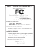
DECLARATION OF CONFORMITY Per FCC Part 2 Section 2.1077(a) Responsible PartName: Address: G.B.T. INC. (U.S.A.) 17358 Railroad Street City of Industry, CA 91748 Phone/Fax No: (818) 854-9338/ (818) 854-9339 hereby declares that the product Product Name: Motherboard Model Number: GA-8PE667 Ultra2 / GA-8PE667 Pro Conforms to the following specifications: FCC Part 15, Subpart B, Section 15.107(a) and Section 15.
GA-8PE667 Ultra2 / Pro P4 Titan 667 Motherboard USER'S MANUAL Pentium®4 Processor Motherboard Rev.
English Table of Content Item Checklist .......................................................................................... 4 WARNING! .............................................................................................. 4 Chapter 1 Introduction ............................................................................. 5 Features Summary ....................................................................................... 5 GA-PE667 Ultra 2 / Pro Motherboard Layout ....................
PC Health Status ........................................................................................ 53 Frequency/Voltage Control ......................................................................... 55 Top Performance ........................................................................................ 57 Select Language ........................................................................................ 58 Load Fail-Safe Defaults ............................................................
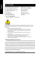
English Item Checklist The GA-8PE667 Ultra2 /Pro motherboard IDE cable x1 / Floppy cable x 1 * CD for motherboard driver & utility GA-8PE667 Ultra2 /Pro user's manual IDE cable x3 / Floppy cable x 1 ** 4 Port USB Cable x 1 Quick PC Installation Guide RAID Manual ** SATA cable x2 ** Audio combo kit x1 ** SATA RAID Manual ** Motherboard Settings Label SPDIF Kit x1(SPD-KIT) * I/O Shield GC-SATA Card (Optional) ** (Manual ; SATA cable x1 ; Power cable x 1) Computer motherboards and expansion cards con
Features Summary Form Factor Motherboard CPU Chipset Memory I/O Control Slots On-Board IDE On-Board Peripherals 30.5cm x 24.4cm ATX size form factor, 4 layers PCB. GA-8PE667 Series Motherboard: GA-8PE667 Ultra2 and GA-8PE667 Pro Socket 478 for Intel® Micro FC-PGA2 Pentium® 4 processor Intel Pentium®4 533MHz/400MHz FSB Support Intel ® Pentium ® 4 (Northwood, 0.
English Hardware Monitor CPU/Power/System Fan Revolution detect CPU/Power/System Fan Control CPU Overheat Warning System Voltage Detect On-Board Sound Realtek ALC650 CODEC Line Out / 2 front speaker Line In / 2 rear speaker(by s/w switch) Mic In / center& subwoofer(by s/w switch) SPDIF out / SPDIF In CD In / AUX In / Game port On-Board RAID ** Onboard Promise PDC20276 Supports data striping (RAID 0) or mirroring (RAID 1) Supports concurrent dual ATA133 IDE controller operation Support ATAPI mode for C
PS/2 Keyboard interface and PS/2 Mouse interface Licensed AWARD BIOS, 4M bit x 2 FWH ** English PS/2 Connector BIOS Licensed AWARD BIOS, 3M bit x 2 FWH * Supports Dual BIOS Supports Multi Language Supports Face Wizard Additional Features Supports Q-Flash PS/2 Keyboard power on by password PS/2 Mouse power on External Modem wake up STR(Suspend-To-RAM) Wake on LAN (WOL) AC Recovery Poly fuse for keyboard over-current protection USB KB/Mouse wake up from S3 Supports @BIOS Supports EasyTune 4 Supports clear
F_AUDIO NB-FAN CLR_PWD MIC_IN LINE_OUT LINE_IN GAME SOCKET478 IDE1 COMB ATX_12V IDE2 GA-8PE667 Ultra2 / Pro LPT1 COMA ATX RAM_LED FLOPPY CPU_FAN PWR_FAN KB_MS SYS_FAN CD_IN Intel 845PE AC97 SPDIF_IN ICH4 PCI2 PCI4 MAIN BACKUP BIOS BIOS SCR BATTERY PCI3 IR/CIR AUX_IN PCI1 CI SPDIF_O AGP DDR3 P4 Titan667 DDR1 Kinnereth-R* Kenai-32** 2X_DET DDR2 LAN USB PDC20276** SUR_CEN IDE4** PCI5 IDE3** PCI6 SIL3112A** ITE8712 S_ATA1** CNR** S_ATA2** F_USB1 F_USB2 Ser
CPUCLK+/-(100/133MHz) Pentium 4 CPU AGP 4X English Block Diagram System Bus 400/533MHz AGPCLK (66MHz) DDR RAM 266/333 MHz Intel 82845PE 6 PCI MCHCLK+/-(100/133MHz) 66 MHz 33 MHz 14.318 MHz 48 MHz Kenai-32** Kinnereth-R* RJ45 GMCHCLK+/-(66MHz) BIOS Intel ICH 4 Game Port LPC BUS ITE8712 Floppy LPT Port Promise** PDC20276 AC97 Link PCICLK (33MHz) Serial ATA** ATA133/RAID** IDE Channels Serial ATA** Channels PS/2 KB/Mouse 24 MHz 33 MHz ATA33/ 6 USB 66/100 (2.0/1.
English GA-8PE667 Ultra2 / Pro Motherboard - 10 -
English Chapter 2 Hardware Installation Process To set up your computer, you must complete the following steps: Step 1- Install the Central Processing Unit (CPU) Step 2- Install memory modules Step 3- Install expansion cards Step 4- Connect ribbon cables, cabinet wires, and power supply Step1 Step4 Step 2 Step 4 Step 4 Step 4 Step3 Congratulations you have accomplished the hardware installation! Turn on the power supply or connect the power cable to the power outlet.
English Step 1: Install the Central Processing Unit (CPU) Before installing the processor , adhere to the following warning: If you do not match the CPU socket Pin 1 and CPU cut edge well, it will cause improper installation. Please change the insert orientation. Please make sure the CPU type is supported by the motherboard. Step 1-1: CPU Installation Angling the rod to 650 Socket Actuation Lever 1. Angling the rod to 65-degree maybe feel a 2. Pull the rod to the 90-degree directly.
English Step 1-2 : CPU Heat Sink Installation Before installing the CPU Heat Sink , adhere to the following warning: 1.Please use Intel approved cooling fan. 2.We recommend you to apply the thermal tape to provide better heat conduction between your CPU and heatsink. (The CPU cooling fan might stick to the CPU due to the hardening of the thermal paste.
English Step 2: Install memory modules Before installing the processor and heatsink, adhere to the following warning: When DIMM LED is ON, do not install/remove DIMM from socket. Please note that the DIMM module can only fit in one direction due to the one notches. Wrong orientation will cause improper installation. Please change the insert orientation. The motherboard has 3 dual inline memory module (DIMM) sockets, but it can only support a maximum of 4 banks of DDR memory.
English 1. The DIMM slot has a notch, so the DIMM memory module can only fit in one direction. 2. Insert the DIMM memory module vertically into the DIMM slot. Then push it down. 3. Close the plastic clip at both edges of the DIMM slots to lock the DIMM module. Reverse the installation steps when you wish to remove the DIMM module.
English Step 3: Install expansion cards 1. Read the related expansion card’s instruction document before install the expansion card into the computer. 2. Remove your computer’s chassis cover, necessary screws and slot bracket from the computer. 3. Press the expansion card firmly into expansion slot in motherboard. 4. Be sure the metal contacts on the card are indeed seated in the slot. 5. Replace the screw to secure the slot bracket of the expansion card. 6. Replace your computer’s chassis cover. 7.
Step 4-1 : I/O Back Panel Introduction PS/2 Keyboard and PS/2 Mouse Connector PS/2 Mouse Connector (6 pin Female) This connector supports standard PS/2 keyboard and PS/2 mouse. PS/2 Keyboard Connector (6 pin Female) Parallel Port and Serial Ports (COMA/COMB) Parallel Port (25 pin Female) This connector supports 2 standard COM ports and 1 Parallel port. Device like printer can be connected to Parallel port ; mouse and modem etc can be connected to Serial ports.
English Game /MIDI Ports This connector supports joystick, MIDI keyboard and other relate audio devices. Joystick/ MIDI (15 pin Female) Audio Connectors Line Out (Front Speaker) MIC In (Center and Subwoofer) After install onboard audio driver, you may connect speaker to Line Out jack, micro phone to MIC In jack. Device like CD-ROM , walkman etc can be connected to Line-In jack. Please note: You are able to use 2-/4-/6- channel audio feature by S/W selection.
1 3 5 12 2 10 6 21 22 14 19 23 20 24 7 26 4 18 25 15 8 17 11 27 16 1) ATX_12V 2) ATX Power 3) CPU_FAN 4) SYS_FAN 5) PWR_FAN 6) NB_FAN 7) IDE1/IDE2 8) IDE3/IDE4 ** 9) S_ATA1/S_ATA2 ** 10) FDD 11) F_PANEL 12) RAM_LED 13) PWR_LED 14) 2X_DET 9 13 15) IR/CIR 16) F_USB1/F_USB2 17) WOL 18) SCR 19) SPDIF_O 20) SPDIF_IN 21) F_AUDIO 22) CD_IN 23) AUX_IN 24) SUR_CEN 25) CI 26) CLR_PWD 27) BATTERY * For GA-8PE667 Pro Only ** For GA-8PE667 Ultra2 Only - 19 - Hardware Installation Process English Step 4-2 :Con
English 1) ATX_12V ( +12V Power Connector) This connector (ATX _12V) suppliesthe CPU operation voltage (Vcore). If this " ATX_ 12V connector" is not connected, system cannot boot. 2 4 1 3 Pin No. 1 2 3 4 Definition GND GND +12V +12V 2) ATX_POWER (ATX Power) AC power cord should only be connected to your power supply unit after ATX power cable and other related devices are firmly connected to the mainboard. 11 20 GA-8PE667 Ultra2 / Pro Motherboard - 20 - 1 10 Pin No.
Please note, a proper installation of the CPU cooler is essential to prevent the CPU from running under abnormal condition or damaged by overheating.The CPU fan connector supports Max. current up to 600 mA. Pin No. 1 2 3 1 Definition GND +12V Sense 4) SYS_FAN (System FAN Connector) This connector allows you to link with the cooling fan on the system case to lower the system temperature. 1 - 21 - Pin No.
English 5) PWR_FAN (Power Fan Connector) This connector allows you to link with the cooling fan on the system case to lower the system temperature. 1 Pin No. 1 2 3 Definition GND +12V Sense 6) NB_FAN If you installed wrong direction, the Chip Fan will not work. Sometimes will damage the Chip Fan. (Usually black cable is GND) 1 GA-8PE667 Ultra2 / Pro Motherboard - 22 - Pin No.
English 7) IDE1/ IDE2(IDE1/IDE2 Connector) Please connect first harddisk to IDE1 and connect CDROM to IDE2. The red stripe of the ribbon cable must be the same side with the Pin1. 2 1 IDE1 39 IDE2 40 8) IDE3 /IDE4 (RAID/ATA133,Green Connectorr)** The rad stripe of the ribbn cable must be the same side with the Pin1. If you wish to use IDE3 and IDE4, please use it in unity with BIOS (either RAID or ATA133). Then, install the correct driver to have proper operation.
English 9) S_ATA1/S_ATA2 (Serial ATA Connector)** You can connect the Serial ATA device to this connector, it provides you high speed transfer rates (150MB/sec). 7 1 Pin No. 1 2 3 4 5 6 7 Definition GND TXP TXN GND RXN RXP GND 10)FDD (Floppy Connector) Please connect the floppy drive ribbon cables to FDD. It supports 360K,720K,1.2M,1.44M and 2.88Mbytes floppy disk types. The red stripe of the ribbon cable must be the same side with the Pin1.
Please connect the power LED, PC peaker, reset switch and power switch etc of your chassis front panel to the F_PANEL connector according to the pin assignment above.
PWR_LED is connect with the system power indicator to indicate whether the system is on/off. It will blink when the system enters suspend mode. If you use dual color LED, power LED will turn to another color. 1 Pin No. 1 2 3 Definition MPD+ MPDMPD- 8)2X_DET When an AGP 2X (3.3V) card is installed the 2X_DET will light up, indicating a nonsupported graphics card is inserted. Informing users that system might not boot up normally due to AGP 2X (3.3V) is not supported by the chipset.
Make sure the pin 1 on the IR device is aling with pin one the connector. To enable the IR/CIR function on the board, you are required to purchase an option IR/CIR module. For detail information please contact your autherized Giga-Byte distributor. To use IR function only, please connect IR module to Pin1 to Pin5. 10 5 6 1 Pin No.
English 17)WOL (Wake On Lan) This connector allows the remove servers to manage the system that installed this mainboard via your network adapter which also supports WOL. Pin No. 1 2 3 1 Definition +5V SB GND Signal 18) SCR (Smart Card Reader Header,Black Connector) This MB supports smart card reader. To enable smart card reader function an optional smart card reader box is required. Please contact your autherized distributor. GA-8PE667 Ultra2 / Pro Motherboard 10 5 6 1 - 28 - Pin No.
The SPDIF output is capable of providing digital audio to external speakers or compressed AC3 data to an external Dolby Digital Decoder. Use this feature only when your stereo system has digital input function. 1 Pin No. 1 2 3 Definition VCC SPDIF OUT GND 20) SPDIF_IN Use this feature only when your device has digital output function. 1 - 29 - Pin No.
English 21) F_AUDIO (F_AUDIO Connector) If you want to use Front Audio connector, you must remove 5-6, 9-10 Jumper. In order to utilize the front audio header, your chassis must have front audio connector. Also please make sure the pin assigment on the cable is the same as the pin assigment on the MB header. To find out if the chassis you are buying support front audio connector, please contact your dealer. 10 9 2 1 Pin No.
English 23) AUX_IN ( AUX In Connector) Connect other device(such as PCI TV Tunner audio out)to the connector. 1 Pin No. 1 2 3 4 Definition AUX-L GND GND AUX_R 24) SUR_CEN Please contact your nearest dealer for optional SUR_CEN cable. 2 6 1 5 - 31 - Pin No.
English 25) CI (CASE OPEN) This 2 pin connector allows your system to enable or disable the “case open” item in BIOS if the system case begin remove. Pin No. Definition 1 Signal 2 GND 1 26) CLR_PWD When Jumper set to "open", the password that set will be cleared. On the contrary when Jumper set to "close", the current status remains. PS, the function offers a solution for users who forget the password.
English 27) BATTERY (Battery) + CAUTION Danger of explosion if battery is incorrectly replaced. Replace only with the same or equivalent type recommended by the manufacturer. Dispose of used batteries according to the manufacturer’s instructions. If you want to erase CMOS... 1.Turn OFF the computer and unplug the power cord. 2.Remove the battery, wait for 30 second. 3.Re-install the battery. 4.Plug the power cord and turn ON the computer.
English GA-8PE667 Ultra2 / Pro Motherboard - 34 -
BIOS Setup is an overview of the BIOS Setup Program. The program that allows users to modify the basic system configuration. This type of information is stored in battery-backed CMOS RAM so that it retains the Setup information when the power is turned off. ENTERING SETUP After power on the computer,pressing immediately during POST (Power On Self Test)itwillallowyouto enter standard BIOS CMOS SETUP. If you require more advanced BIOS settings, please go to “advanced BIOS” setting menu.
English GETTING HELP Main Menu The on-line description of the highlighted setup function is displayed at the bottom of the screen. Status Page Setup Menu / Option Page Setup Menu Press F1 to pop up a small help window that describes the appropriate keys to use and the possible selections for the highlighted item. To exit the Help Window press . The Main Menu (For example: BIOS Ver. : F1) Once you enter Award BIOS CMOS Setup Utility, the Main Menu (Figure 1) will appear on the screen.
Power Management Setup English z This setup page includes all the items of Green function features. z PnP/PCI Configurations This setup page includes all the configurations of PCI & PnP ISA resources. z PC Health Status This setup page is the System auto detect Temperature, voltage, fan, speed. z Frequency/Voltage Control This setup page is control CPU’s clock and frequency ratio.
English Standard CMOS Features CMOS Setup Utility-Copyright (C) 1984-2002 Award Software Standard CMOS Features Date (mm:dd:yy) Thu, Feb 21 2002 Item Help Time (hh:mm:ss) 22:31:24 `IDE Primary Master [Press Enter None] Change the day, month, `IDE Primary Slave [Press Enter None] year `IDE Secondary Master [Press Enter None] `IDE Secondary Slave [Press Enter None] Sun. to Sat. Drive A [1.44M, 3.5”] Menu Level X Drive B [None] Jan. to Dec.
The category identifies the types of hard disk from drive C to F that has been installed in the computer.There are two types: auto type, and manual type. Manual type is user-definable; Auto type which will automatically detect HDD type. Note that the specifications of your drive must match with the drive table. The hard disk will not work properly if you enter improper information for this category. If you select User Type, related information will be asked to enter to the following items.
English )Halt on The category determines whether the computer will stop if an error is detected during power up. NO Errors The system boot will not stop for any error that may be detected and you will be prompted. AllErrors Whenever the BIOS detects a non-fatal error the system will be stopped. All, But Keyboar The system boot will not stop for a keyboard error; it will stop for all other errors.
English Advanced BIOS Features CMOS Setup Utility-Copyright (C) 1984-2002 Award Software Advanced BIOS Features SATA/RAID / SCSI Boot Order** [RAID,SCSI] Item Help First Boot Device [Floppy] Menu Level X Second Boot Device [HDD-0] Third Boot Device [CDROM] Boot Up Floppy Seek [Disabled] Password Check [Setup] #CPU Hyper-Threading [Enabled] InitDisplayFirst [AGP] KLJI: Move Enter:Select +/-/PU/PD:Value F10:Save ESC:Exit F1:General Help F3:Language F5:Previous Values F6:Fail-Safe Defaults F
English USB-ZIP Select your boot device priority by USB-ZIP. USB-FDD Select your boot device priority by USB-FDD. USB-HDD Select your boot device priority by USB-HDD. ZIP Select your boot device priority by ZIP. Disabled Disabled this function. )Boot Up Floppy Seek 0During POST, BIOS will determine the floppy disk drive installed is 40 or 80 tracks. 360 K type is 40 tracks 720 K, 1.2 M and 1.44 M are all 80 tracks.
English Integrated Peripherals CMOS Setup Utility-Copyright (C) 1984-2002 Award Software Integrated Peripherals On-Chip Primary PCI IDE [Enabled] Item Help On-Chip Secondary PCI IDE [Enabled] Menu Level X IDE1 Conductor Cable [Auto] IDE2 Conductor Cable [Auto] USB Controller [Enabled] USB Keyboard Support [Disabled] USB Mouse Support [Disabled] AC97 Audio [Auto] Onboard H/W SATA** Serial ATA Function** Onboard ATA/RAID Device * RAID Controller Function * [Enabled] [RAID] [Enabled] [ATA]
English )On-Chip Primary PCI IDE 0When enabled, allows you to use the onboard primary PCI IDE. If a hard disk controller card is used, set at Disabled. Enabled Enable onboard 1st channel IDE port. (Default value) Disabled Disable onboard 1st channel IDE port. )On-Chip Secondary PCI IDE 0When enabled, allows you to use the onboard secondary PCI IDE. If a hard disk controller card is used, set at Disabled. Enabled Enable onboard 2nd channel IDE port.
Enabled Enabled USB Mouse Support. Disabled Disabled USB Mouse Support. (Default value) English )USB Mouse Support )AC97 Audio Auto BIOS will automatically detect onboard AC97 Audio. (Default value) Disabled Disabled AC97 Audio. )Onboard H/W SATA ** 0Disable this option if you are not using the onboard Serial ATA feature. Enabled Enabled Onboard H/W Serial ATA support.(Default value) Disabled Disabled Onboard H/W Serial ATA.
English )Onboard LAN Boot ROM 0The function is to invoke onboard LAN chip to boot up the system Enable Enable onboard LAN boot ROM function. Disable Disable this function. (Default value) )Onboard Serial Port 1 Auto BIOS will automatically setup the port 1 address. 3F8/IRQ4 Enable onboard Serial port 1 and address is 3F8. (Default value) 2F8/IRQ3 Enable onboard Serial port 1 and address is 2F8. 3E8/IRQ4 Enable onboard Serial port 1 and address is 3E8.
0This feature allows you to select from a given set of parameters if the parallel port uses the onboard I/O controller. 378/IRQ7 Enable On Board LPT port and address is 378.(Default Value) 278/IRQ5 Enable On Board LPT port and address is 278. 3BC/IRQ7 Enable On Board LPT port and address is 3BC. )Parallel Port Mode 0This feature allows you to connect with an advanced print via the port mode it supports. SPP EPP Using Parallel port as Standard Parallel Port .
English )CIR Port Address This feature allows you to select CIR port address or disable it. Disabled Disabled this function. (Default Value) 310 Enabled CIR and Address is 310. 320 Enabled CIR and Address is 320. )CIR Port IRQ (When (When Parallel Port Parallel Port Mode Mode is is set set [ECP [ECP or or ECP+EPP]) ECP+EPP]) This feature allows you to select CIR IRQ , if CIR is enabled. 5 CIR use IRQ 5. 11 CIR use IRQ 11.
English Power Management Setup CMOS Setup Utility-Copyright (C) 1984-2002 Award Software Power Management Setup ACPI Suspend Type [S1(POS)] Item Help Power LED in S1 State [Blinking] Menu Level X Soft-Off by PWR-BTTN [Instant-off ] PME Event Wake Up [Enabled] ModemRingOn/WakeOnLAN [Enabled] Resume by Alarm [Disabled] Ú Date(of Month) Alarm Everyday Ú Time(hh:mm:ss) Alarm 0: 0: 0 Power On By Mouse [Disabled] Power On By Keyboard [Disabled] ÚKB Power On Password Enter AC Back Function
English )ACPI Suspend Type S1(POS) Set ACPI Suspend Type to S1/POS (Power On Suspend). (Default value) S3(STR) Set ACPI Suspend Type to S3/STR (Suspend To RAM). )Power LED in S1 State Blinking In standby mode(S1), power LED will blink. (Default Value) Dual/Off In standby mode(S1): a. If use single color LED, power LED will turn off . b. If use dual color LED, power LED will turn to another color. )Soft-off by PWR-BTTN Instant-off Press power button then Power offinstantly.
You can set "Resume by Alarm" item to enabled and key in Data/time to power on system. Disabled Disable this function. (Default Value) Enabled Enable alarm function to POWER ON system. IfRTC Alarm Lead To Power On is Enabled. Date ( of Month) Alarm : Everyday, 1~31 Time ( hh: mm: ss) Alarm : (0~23) : (0~59) : (0~59) )Power On By Mouse Disabled Disabled this function. (Default value) Mouse Click Set mouse double click to power on system.
English PnP/PCI Configurations CMOS Setup Utility-Copyright (C) 1984-2002 Award Software PnP/PCI Configurations PCI1/PCI5 IRQ Assignment [Auto] Item Help PCI2 /PCI6 IRQ Assignment [Auto] Menu Level X PCI3 IRQ Assignment [Auto] PCI4 IRQ Assignment [Auto] KLJI: Move Enter:Select +/-/PU/PD:Value F10:Save ESC:Exit F1:General Help F3:Language F5:Previous Values F6:Fail-Safe Defaults F7:Optimized Defaults Figure 6: PnP/PCI Configurations )PCI1/PCI5 IRQ Assignment Auto Auto assign IRQ to PCI 1/ PCI 5
English PC Health Status CMOS Setup Utility-Copyright (C) 1984-2002 Award Software PC Health Status Reset Case Open Status [Disabled] Item Help Case Opened No Menu Level X VCORE 1.448V +1.5V 1.448V +3.3V 3.312V + 5V 5.080 V +12V 11.
English )Current CPU Temperature (°C) Detect CPU Temp. automatically. )Current CPU FAN / POWER / SYSTEM FAN Speed (RPM) Detect Fan speed status automatically. )CPU Warning Temperature 60°C / 140°F Monitor CPU Temp. at 60°C / 140°F. 70°C / 158°F Monitor CPU Temp. at 70°C / 158°F. 80°C / 176°F Monitor CPU Temp. at 80°C / 176°F. 90°C / 194°F Monitor CPU Temp. at 90°C / 194°F. Disabled Don’t monitor current temperature.
English Frequency/Voltage Control CMOS Setup Utility-Copyright (C) 1984-2002 Award Software Frequency/Voltage Control CPU Clock Ratio [15X] Item Help CPU Host Clock Control [Disable] Menu Level X ÚCPU Host Frequency(MHz) 100 ÚFixed PCI/AGP Frequency 33/66 Host/DRAM Clock ratio [Auto] Memory Frequency(MHz) 266 PCI/AGP Frequency(MHz) 33/66 DIMM OverVoltage Control [Normal] AGP OverVoltage Control [Normal] CPU Voltage Control [Normal] Normal CPU Vcore 1.
English )CPU Host Frequency (MHz) 100MHz ~ 355MHzSet CPU Host Clock from 100MHz to 355MHz. )Fixed PCI/AGP Frequency You can choose those mode to adjust PCI/AGP frequency. (Select PCI/AGP frequency asynchronous with CPU frequency). )Host/DRAM Clock Ratio for FSB(Front Side Bus) frequency=400MHz, 2.0 Memory Frequency = Host clock X 2.0. 2.66 Memory Frequency = Host clock X 2.66. Auto Set Memory frequency by DRAM SPD data. (Default value) for FSB(Front Side Bus) frequency=533MHz, 2.
English Top Performance CMOS Setup Utility-Copyright (C) 1984-2002 Award Software `Standard CMOS Features Select Language `Advanced BIOS Features Load Fail-Safe Defaults `Integrated Peripherals Load Optimized Defaults `Power Management Setup Load Top Performance Defaults `PC Health Status Set User Password `Frequency/Voltage Control Save & Exit Setup Top Performance KL:Move ESC:Quit ESC: Abort F8:Dual BIOS /Q-Flash Exit Without Saving ENTER: Accept F3:Change Language Disabled.................
English Select Language CMOS Setup Utility-Copyright (C) 1984-2002 Award Software `Standard CMOS Features Select Language `Advanced BIOS Features Load Fail-Safe Defaults `Integrated Peripherals Load Optimized Defaults `Power Management Setup Set Supervisor Password `PnP/PCI Configurations Set User Password `PC Health Status Save & Exit Setup `Frequency/Voltage Control Exit Without Saving u Top Performance ESC:Quit F3:Change Language F8:Dual BIOS /Q-Flash F10:Save & Exit Setup Figure 10:S
English Load Fail-Safe Defaults CMOS Setup Utility-Copyright (C) 1984-2002 Award Software `Standard CMOS Features Select Language `Advanced BIOS Features Load Fail-Safe Defaults `Integrated Peripherals Load Optimized Defaults `Power Management Setup Set Supervisor Password `PnP/PCI Configurations Set User Password `PC Health Status Save & Exit Setup Defaults? Figure 11 o ll -Safe Defaul ts `Frequency/Vo l: taL gLoad ead CoF na ti rFail-Safe o Ex(Y/N)?N it Without Saving Top Performance ESC:Quit
English Load Optimized Defaults CMOS Setup Utility-Copyright (C) 1984-2002 Award Software `Standard CMOS Features Select Language `Advanced BIOS Features Load Fail-Safe Defaults `Integrated Peripherals Load Optimized Defaults `Power Management Setup Set Supervisor Password `PnP/PCI Configurations Set User Password `Frequency/Voltage Control Exit Without Saving 11: LLoad oad FaiOptimized l-Safe DefaultDefaults? s Save & (Y/N)?N `PC HealthFiSgtuarteus Exit Setup Top Performance ESC:Quit F3:Chan
English Set Supervisor/User Password CMOS Setup Utility-Copyright (C) 1984-2002 Award Software `Standard CMOS Features Select Language `Advanced BIOS Features Load Fail-Safe Defaults `Integrated Peripherals Load Optimized Defaults `Power Management Setup Set Supervisor Password `PnP/PCI Configurations Set User Password `PC Health StatusEnter Password: Figure 11: Load Fail-Safe Defaults `Frequency/Voltage Control Save & Exit Setup Exit Without Saving Top Performance ESC:Quit F3:Change Language
English Save & Exit Setup CMOS Setup Utility-Copyright (C) 1984-2002 Award Software `Standard CMOS Features Select Language `Advanced BIOS Features Load Fail-Safe Defaults `Integrated Peripherals Load Optimized Defaults `Power Management Setup Set Supervisor Password `PnP/PCI Configurations Set User Password `PC Health Status Save & Exit Setup `Frequency/Voltage CSave ontrol to CMOS and EXIT Exit(Y/N)? Without SY aving Top Performance ESC:Quit F3:Change Language F8:Dual BIOS /Q-Flash F10:Sav
English Exit Without Saving CMOS Setup Utility-Copyright (C) 1984-2002 Award Software `Standard CMOS Features Select Language `Advanced BIOS Features Load Fail-Safe Defaults `Integrated Peripherals Load Optimized Defaults `Power Management Setup Set Supervisor Password `PnP/PCI Configurations Set User Password `PC Health Status Save & Exit Setup Quit Without Saving (Y/N)? N `Frequency/Voltage Control Exit Without Saving Top Performance ESC:Quit F3:Change Language F8:Dual BIOS /Q-Flash F10
English GA-8PE667 Ultra2 / Pro Motherboard -64-
English Chapter 4 Technical Reference @ BIOS Introduction Gigabyte announces @ BIOS Windows BIOS live update utility Have you ever updated BIOS by yourself? Or like many other people, you just know what BIOS is, but always hesitate to update it? Because you think updating newest BIOS is unnecessary and actually you don’t know how to update it. Maybe not like others, you are very experienced in BIOS updating and spend quite a lot of time to do it. But of course you don’t like to do it too much.
English Easy TuneTM 4 Introduction Gigabyte announces EasyTuneTM 4 Windows based Overclocking utility EasyTune 4 carries on the heritage so as to pave the way for future generations. Overclock" might be one of the most common issues in computer field. But have many users ever tried it? The answer is probably "no". Because "Overclock" is thought to be very difficult and includes a lot of technical know-how, sometimes "Overclock" is even considered as special skills found only in some enthusiasts.
What is Face-WizardTM? Face-WizardTM is a windows based utility with user-friendly interface that allows users to change the boot-up logo with picture from Gigabyte Logo Gallery on web site or other compatible picture you have. How does it work? Face-WizardTM allows user to select BIOS on board or file in hard drive, floppy disk , zip, MO or other storage devices and combine the compatible picture you prefer into BIOS. And not only this, Face-WizardTM also helps user to update BIOS in windows mode.
English BIOS Flash Procedure Method 1: We use GA-7VTX motherboard and Flash841 BIOS flash utility as example. Please flash the BIOS according to the following procedures if you are now under the DOS mode. Flash BIOS Procedure: STEP 1: (1) Please make sure your system has installed the extraction utility such as winzip or pkunzip. Firstly you have to install the extraction utility such as winzip or pkunzip for unzip the files.
needed system files to it. Beware: This procedure will erase all the prior data on that floppy, so please proceed accordingly. (3) After the floppy has been formatted completely, please press "Close". -69- Technical Reference English (2) Select the "Quick (erase)" for Format Type, and pick both "Display summary when finished" and "Copy system files", after that press "Start".
English STEP 3: Download BIOS and BIOS utility program. (1) Please go to Gigabyte website http://www.gigabyte.com.tw/index.html, and click "Support". (2) From Support zone, click the "Motherboards BIOS & Drivers".
(4) Select an appropriate BIOS version (For example: F4), and click to download the file. It will pop up a file download screen, then select the "Open this file from its current location" and press "OK". -71- Technical Reference English (3) We use GA-7VTX motherboard as example. Please select GA-7VTX by Model or Chipset optional menu to obtain BIOS flash files.
English (5) At this time the screen shows the following picture, please click "Extract" button to unzip the files. (6) Please extract the download files into the clean bootable floppy disk A mentioned in STEP 2, and press "Extract".
restart the system. The system will boot from the floppy disk. Please press key to enter BIOS setup main menu when system is boot up. American Release:09/16/99 Megatrends AMIBIOS (C) 1999 American Megatrend 7VTX F1 Check System Health OK AMD-Athlon(tm)Processor-900MHz Checking NVRAM... 262144KB Wait... Press F1 to enter Dual BIOS Utility. Press ESC to quit Press any key to contiune ( C ) American Megatrends Inc.
English (3) Press "Enter" to enter "BIOS FEATURES SETUP" menu. Use the arrows to highlight the item "1st Boot Device", and then use the "Page Up" or "Page Down" keys to select "Floppy". AMIBIOS SETUP - BIOS FEATURES SETUP ( C ) 2001 American Megatrends, Inc. All Rights Reserved 1st Boot Device : Floppy 2nd Boot Device : IDE-0 3rd Boot Device : CDROM S.M.A.R.T.
files in floppy A. Then type the "BIOS flash utility" and "BIOS file" after A:\>. In this case you have to type "A:\> Flash841 7VTX.F4" and then press "Enter". Starting Windows 98… Microsoft(R) Windows98 © Copyright Microsoft Corp 1981-1999 A:\> dir/w Volume in drive A has no label Volume Serial Number is 16EB-353D Directory of A:\ COMMAND.COM 3 file(s) 0 dir(s) 7VTX.F4 FLASH841.EXE 838,954 bytes 324,608 bytes free A:\> Flash841 7VTX.F4 (2) Now screen appears the following Flash Utility main menu.
English (3) It will pop up a screen and asks "Are you sure to flash the BIOS?" Press [Enter] to continue theprocedure, or press [ESC] to quit. Beware: Please do not turn off the system while you are upgrading BIOS. It will render your BIOS corrupted and system totally inoperative. Are you sure to flash the BIOS? [Enter] to continue Or [Esc] to cancel? (4) The BIOS flash completed. Please press [ESC] to exit Flash Utility.
highly recommend reloading the BIOS defaults after BIOS has been upgraded. This important step resets everything after the flash. (1) Take out the floppy diskette from floppy drive, and then restart the system. The boot up screen will indicate your motherboard model and current BIOS version. American Release:09/16/99 Megatrends AMIBIOS (C) 1999 American Megatrend 7VTX F4 Check System Health OK AMD-Athlon(tm)Processor-900MHz Checking NVRAM... 262144KB Wait... Press F1 to enter Dual BIOS Utility.
English (3) Use the arrows to highlight the item "SAVE & EXIT SETUP" and press "Enter". System will ask "SAVE to CMOS and EXIT (Y/N)?" Press "Y" and "Enter" keys to confirm. Now the system will reboot automatically, the new BIOS setting will be taken effect next boot-up. AMIBIOS SIMPLE SETUP UTILITY - VERSION 1.24b (C) 2001 American Megatrends, Inc.
English Method 2: Dual BIOS / Q-Flash Introduction A. What is Dual BIOS Technology? Dual BIOS means that there are two system BIOS (ROM) on the motherboard, one is the Main BIOS and the other is Backup BIOS. Under the normal circumstances, the system works on the Main BIOS. If the Main BIOS is corrupted or damaged, the Backup BIOS can take over while the system is powered on. This means that your PC will still be able to run stably as if nothing has happened in your BIOS. B.
English b. Dual BIOS / Q-Flash Utility Dual BIOS / Q-Flash Utility V845.4MF3 (C) 2001, GIGA-BYTE Technology Co., LTD. Wide Range Protection :Disabled Halt On BIOS Defects Auto Recovery :Disabled :Enabled Boot From BIOS Recovery :Main BIOS :Main to Backup F3: Load Default F5:Start BIOS Recovery F7: Save And Restart F8: Update BIOS from disk F9:Exit Without Saving F10:Recovery from Disk Use key to toggle setup c.
If the BIOS occurs a checksum error or the Main BIOS occurs a WIDE RANGE PROTECTION error and Halt On BIOS Defects set to Enable, the PC will show messages on the boot screen, and the system will pause and wait for the user’s instruction. If Auto Recovery :Disabled, it will show If Auto Recovery :Enabled, it will show
English C. What is Q-Flash Utility? Q-Flash utility is a pre-O.S. BIOS flash utility enables users to update its BIOS within BIOS mode, no more fooling around any OS. D. How to use Q-Flash Flash? F3: Load Default F5: Start BIOS Recovery Load current BIOS default value. Press F5 to recovery new BIOS version. F7: Save and Restart F9: Exit Without Saving Save revised setting and restart the Exit without changing. computer. F8: Update BIOS from Disk Update boot-up BIOS.
DualBIOS technology is a patented technology from Giga-Byte Technology. The concept of this technology is based on the redundancy and fault tolerance theory. DualBIOSTM technology simply means there are two system BIOSes (ROM) integrated onto the motherboard. One is a main BIOS, and the other is a backup BIOS. The mainboard will operate normally with the main BIOS, however, if the main BIOS is corrupt or damaged for various reasons, the backup BIOS will be automatically used when the system powered-On.
English III. Q: How does DualBIOSTM technology work? Answer: 1. 2. DualBIOSTM technology provides a wide range of protection during the boot up procedure. It protects your BIOS during system POST, ESCD update, and even all the way to PNP detection/assignment. DualBIOSTM provides automatic recovery for the BIOS. When the first BIOS used during boot up does not complete or if a BIOS checksum error occurs, boot-up is still possible.
backup BIOS will take over the boot-up process automatically. Moreover, it will verify the main and backup BIOS checksums when booting-up. DualBIOSTM technology examines the checksum of the main and backup BIOS while the system is powered on to guarantee your BIOS operates properly. 3. Power Users will have the advantage of having two BIOS versions on their mainboard. The benefit is being able to select either version BIOS to suit the performance system needs. 4.
English Method 3: If you don’t have DOS boot disk, we recommend that you used Gigabyte @BIOSTM program to flash BIOS. Follow the setup that showing on the scween to install the Utility. Press here. 2.Click"Start"-"Programs""GIGABYTE"-"@BIOS" 1.Click "@BIOS (B02102201). (1) Click "3". (2) Click here. 3. Please select @BIOS sever site, then Click "OK". (4) (3) Methods and steps: I. Update BIOS through Internet a. Click "Internet Update" icon b. Click "Update New BIOS" icon c. Select @BIOSTM sever d.
English II. Update BIOS NOT through Internet: a. Do not click "Internet Update" icon b. Click "Update New BIOS" c. Please select "All Files" in dialog box while opening the old file. d. Please search for BIOS unzip file, downloading from internet or any other methods (such as: 8PE667U2.F1). e. Complete update process following the instruction. III. Save BIOS In the very beginning, there is "Save Current BIOS" icon shown in dialog box. It means to save the current BIOS version. IV.
English Revision HistoryAudio Function Introuction 2-/4-/6-Channel The installation of windows 98SE/2K/ME/XP is very simple. Please follow next step to install the function! Stereo Speakers Connection and Settings: W e recommend that you use the speaker with amplifier to acqiire the best sound effect if the stereo output is applied. STEP 1: Connect the stereo speakers or earphone to “Line Out”. Line Out STEP 2 : After installation of the audio driver, you’ll find an icon on the taskbar’s status area.
STEP 1 : Connect the front channels to “Line Out”,the rear channels to “Line In”. Line Out Line In STEP 2 : After installation of the audio driver, you’ll find an icon on the taskbar’s status area. Click the audio icon “Sound Effect” from the windows tray at the bottom of the screen. STEP 3 : Select “Speaker Configuration”, and choose the “4 channels for 4 speakers out put”. Disable “Only SURROUND-KIT”, and press “OK”.
English Basic 6 Channel Analog Audio Output Mode Use the back audio panel to connect the audio output without any additional module. STEP 1 : Line Out Connect the front channels to “Line Out”,the rear channels to “Line In”, and the Center/Subwoofer channels to “MIC In . ” STEP 2 : After installation of the audio driver, you’ll find an icon on the taskbar’s status area. Click the audio icon “Sound Effect” from the windows tray at the bottom of the screen.
(Audio Combo Kit provides SPDIF output port : optical & coaxis and SURROUND-KIT : Rear R/L & CEN / Subwoofer) SURROUND-KIT access analog output to rear channels and Center/Subwoofer channels. It is the best solution if you need 6 channel output, Line In and MIC at the same time. "SURROUND-KIT” is included in the GIGABYTE unique "Audio Combo Kit” as picture. STEP 1 : Insert the “Audio Combo Kit” in the back of the case , and fix it with the screw. STEP 2 : Connect the ”SURROUND-KIT” to SUR_CEN on the M/B.
English STEP 3 : Connect the front channels to back audio panel’s “Line Out”, the rear channels to SURROUND-KIT’s REAR R/L, and the Center/Subwoofer channels to SURROUND-KIT’s SUB CENTER. STEP 4 : Click the audio icon “Sound Effect” from the windows tray at the bottom of the screen. STEP 5 : Select “Speaker Configuration”, and choose the “6 channels for 5.1 speakers out put”. Enable “Only SURROUND-KIT” and press “OK”.
English SPDIF Output Device (Optional Device) A “SPDIF output” device is available on the motherboard. Cable with rear bracket is provided and could link to the “SPDIF output” connector (As picture.) For the further linkage to decoder, rear bracket provides coaxial cable and Fiber connecting port. 1 . Connect the SPDIF output device to the rear bracket of PC, and fix it with screw. 2. Connect SPDIF wire to the motherboard. 3 . Connect co-axial or optical output to the SPDIF decoder.
English GA-8PE667 Ultra2 /Pro Motherboard -94-
English Revision History Chapter 5 Appendix Install Drivers Picture below are shown in Windows XP (IUCD ver 2.21) Insert the driver CD-title that came with your motherboard into your CD-ROM drive, the driver CD-title will auto start and show the installation guide. If not, please double click the CD-ROM device icon in "My computer", and execute the setup.exe. INSTALL CHIPSET DRIVER This page shows the drivers that need to be installed for the system.
English Driver install finished!! you have to reboot system!! Item Description Intel Chipset Software Installation Utility Tell the operating system how the chipset components will be configured Intel Application Accelerator Designed to improve performance of the storage sub-system and overall system performance USB Path for WinXP This patch driver can help you to resolve the USB device wake up S3 hang up issue in XP Intel 82562/82562EX/82540EM LAN Driver For Intel(R) PRO/10/100/1000/Wireless Ethe
This page reveals the value-added software developed by Gigabyte and its worldwide partners.
English SOFTWARE INFORMATION This page list the contects of softwares and drivers in this CD title. HARDWARE INFORMATION This page lists all device you have for this motherboard.
English CONTACT US Contact us via the information in this page all over the world. y U.K G.B.T. TECH. CO. LTD. Tel: 44-1908-362700 Fax: 44-1908-362709 E-mail:support@gbt-tech.co.uk Web Address: www.gbt-tech.co.uk y The Netherlands Giga-Byte Technology B.V. Address: Postbus 1385, 5602 BJ, Eindhoven, The Netherlands Tel: +31 40 290 2088 y Taiwan Fax: +31 40 290 2089 Gigabyte Technology Co., Ltd. E-mail:info@giga-byte.nl Address: No.6, Bau Chiang Road, Hsin-Tien, Taipei Hsien, Taiwan, R.O.C.
English Acronyms Acronyms Meaning ACPI APM Advanced Configuration and Power Interface Advanced Power Management AGP AMR Accelerated Graphics Port Audio Modem Riser ACR BIOS Advanced Communications Riser Basic Input / Output System CPU CMOS Central Processing Unit Complementary Metal Oxide Semiconductor CRIMM CNR Continuity RIMM Communication and Networking Riser DMA DMI Direct Memory Access Desktop Management Interface DIMM DRM Dual Inline Memory Module Dual Retention Mechanism DRAM DDR Dy
Meaning Input Output Advanced Programmable Input Controller ISA LAN Industry Standard Architecture Local Area Network I/O LBA Input / Output Logical Block Addressing LED MHz Light Emitting Diode Megahertz MIDI MTH Musical Instrument Digital Interface Memory Translator Hub MPT NIC Memory Protocol Translator Network Interface Card OS OEM Operating System Original Equipment Manufacturer PAC POST PCI A.G.P.
English Technical Support/RMA Sheet Customer/Country: Company: Contact Person: E-mail Add. : Model name/Lot Number: BIOS version: O.S./A.S.: Hardware Model name Mfs. PCB revision: Configuration CPU Memory Brand Video Card Audio Card HDD CD-ROM / DVD-ROM Modem Network AMR / CNR Keyboard Mouse Power supply Other Device Problem Description: GA-8PE667 Ultra2 / Pro Motherboard Phone No.
English Troubleshooting If you encounter any trouble during boot up, please follow the troubleshooting procedures . START Turn off the power and unplug the AC power cable, then remove all of the add-on cards and cables from motherboard. Please make sure motherboard & chassis are not short ? Yes Please isolate the short pin. No Failure has been excluded. Please make sure all jumper settings (such as CPU system bus speed, frequency ratio, voltage and etc.) are set properly.
English A Is memory LED on and CPU fan running? No The problem could be caused by power supply, CPU, memory or CPU/ memory socket itself. Yes Failure has been excluded. No Check if there is display. Yes Perhaps your VGA card / VGA slot or monitor is defective. Failure has been excluded. Turn off the system. Reboot after keyboard and mouse have been plugged in. No Check if keyboard is working properly. It is possible that your keyboard or keyboard connector is defective.
English -105- Memo
English GA-8PE667 Ultra2 / Pro Motherboard -106-
English -107- Memo
English GA-8PE667 Ultra2 / Pro Motherboard -108-