GA-3PXSL-RH AMD Socket AM2 Motherboard USER’S MANUAL AMD®AM2 Processor Motherboard Rev. 1003 * The WEEE marking on the product indicates this product must not be disposed of with user's other household waste and must be handed over to a designated collection point for the recycling of waste electrical and electronic equipment!! * The WEEE marking applies only in European Union's member states.
English GA-3PXSL-RH Motherboard Table of Content Item Checklist ......................................................................................... 4 WARNING! ............................................................................................... 4 Chapter 1 Introduction ............................................................................ 5 1.1.Features Summary ................................................................................ 5 1.2GA-3PXSL-RH Motherboard Components ...
Chapter 4 Application Driver Installation ............................................... 55 A.NVDIA Chipset Driver Installation ............................................................................... 55 B.nVIDIA VGA Driver Installation .................................................................................... 61 C.Marvell LAN Driver Installation .................................................................................. 63 D.DirectX 9.0 Driver Installation .........................
English GA-3PXSL-RH Motherboard Item Checklist The GA-3PXSL-RH motherboard IDE (ATA100 ) cable x 1 / Floppy cable x 1 Serial ATA cable x 4 I/O Shield Kit CD for motherboard driver & utility GA-3PXSL-RH user’s manual WARNING! Computer motherboards and expansion cards contain very delicate Integrated Circuit (IC) chips. To protect them against damage from static electricity, you should follow some precautions whenever you work on your computer. 1. Unplug your computer when working on the inside. 2.
Introduction Chapter 1 Introduction 1.1. Features Summary Form Factor CPU 12” x 9.
English GA-3PXSL-RH Motherboard BIOS Licensed Award BIOS on 4MB flash ROM SMBIOS Spec. Rev 2.3.3.
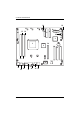
Introduction 1.2 GA-3PXSL-RH Motherboard Components 1. 2. CPU NVIDIA GeForce 6150 26. 27. DIMMB1 DIMMA2 3. 4. NVIDIA nForce 430 ITE 8712F-A 28. 29. DIMMB2 PCI-E x1 Slot 5. 6. BIOS Flash Marvel 88E1116 GbE PHY 30. 31. PCI-E x16 Slot PCI 3 Slot (32bit/33MHz) 7. 8. Marvel 8056 GbE IDE1 Connector 32. 33. PCI 2 Slot (32bit/33MHz) PCI 1 Slot (32bit/33MHz) 9. 10. IDE2 Connector Floppy Connector 34. 35. PS/2 Connectors USB ports 11. 12. SATA1 Connector SATA2 Connector 36. 37.
English GA-3PXSL-RH Motherboard 23 24 21 40 20 22 27 25 10 9 12 11 15 43 18 17 14 13 8 42 3 41 1 16 30 2 31 6 28 26 35 36 37 38 33 29 7 4 34 32 39 39 8 5 19
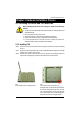
Hardware Installation Process Chapter 2 Hardware Installation Process 2-1: Installing Processor and CPU Haet Sink Before installing the processor and cooling fan, adhere to the following cautions: 1. The processor will overheat without the heatsink and/or fan, resulting in permanent irreparable damage. 2. Never force the processor into the socket. 3. Apply thermal grease on the processor before placing cooling fan. 4. Please make sure the CPU type is supported by the motherboard. 5.
English GA-3PXSL-RH Motherboard 2-1-2: Installing CPU Cooler Fan Fig.1 Before installing the CPU cooler fan, please first add an even layer of heat paste on the surface of the CPU. Install all the CPU cooler components (Please refer to the cooler manual for detailed installation instructions). Fig.2 Please connect the CPU cooler fan power connector to the CPU_FAN connector located on the motherboard.
Hardware Installation Process 2-2: Install memory modules GA-3PXSL-RH has 4 dual inline memory module (DIMM) socets. It supports the Dual Channel Technology. The BIOS will automatically detects memory type and size. To install the memory module, just push it vertically into the DIMM socket .The DIMM module can only fit in one direction due to the notch. Wrong orientation will cause improper installation. Please change the insert orientation. Memory size can vary between sockets.
English GA-3PXSL-RH Motherboard Installation Step: 1. Unlock a DIMM socket by pressing the retaining clips outwards. 2. Aling a DIMM on the socket such that the notch on the DIMM exactly match the notches in the socket. 3. Firmly insert the DIMMinto the socket until the retaining clips snap back in place. 4. When installing the DIMM into the DIMM socket, we recommend to populate one DIMM in Channel A module and one in Channel B module for best performance.
Hardware Installation Process 2-3: Install expansion cards 1. Read the related expansion card’s instruction document before install the expansion card into the computer. 2. Remove your server’s chassis cover, necessary screws and slot bracket from the computer. 3. Press the expansion card firmly into expansion slot in motherboard. 4. Be sure the metal contacts on the card are indeed seated in the slot. 5. Replace the screw to secure the slot bracket of the expansion card. 6.
English GA-3PXSL-RH Motherboard 2-4: Connect ribbon cables, cabinet wires, and power supply 2-4-1 : I/O Back Panel Introduction 14
Hardware Installation Process PS/2 Keyboard and PS/2 Mouse Connector To install a PS/2 port keyboard and mouse, plug the mouse to the upper port (green) and the keyboard to the lower port (purple). USB Port Before you connect your device(s) into USB connector(s), please make sure your device(s) such as USB keyboard, mouse, scanner, zip, speaker...etc. have a standard USB interface. Also make sure your OS supports USB controller.
English GA-3PXSL-RH Motherboard 2-5: Connectors & Jumper Setting Introduction O P S R E D C H GF I Q A L T K J B N M A) B) C) D) E) F) G) H) I) J) K) L) ATX ATX _12V IDE1 IDE2 FDD SATA1 SATA2 SATA3 SATA4 F_USB2 F_USB3 F_Panel1 M) N) O) P) Q) R) S) T) 16 COMB Battery SYS_FAN1 SYS_FAN2 SYS_FAN3 SYS_FAN4 CPU_FAN CLR_CMOS (CMOS Clear Jumper)
Connector Introduction A) ATX (ATX Power Connector) 12 24 AC power cord should only be connected to your power supply unit after ATX power cable and other related devices are firmly connected 1 to the mainboard. 13 PIN No. Definition 1 +3.3V 2 3 +3.3V GND 4 5 +5V GND 6 7 +5V GND 8 9 POK 5VSB 10 11 +12V +12V 12 13 +3.3V +3.
English GA-3PXSL-RH Motherboard C/D ) IDE1/IDE2 Connector Please connect first harddisk to IDE1. The red stripe of the ribbon cable must be the same side with the Pin1. IDE2 IDE1 2 1 40 39 E) FDD (Floppy Connector) Please connect the floppy drive ribbon cables to FDD. It supports 1.2M,1.44M and 2.88Mbytes floppy disk types. The red stripe of the ribbon cable must be the same side with the Pin1.
Connector Introduction F/ G/ H/ I ) SATA1/ 2/ 3/ 4 (Serial ATA Connectors) You can connect the Serial ATA device to this connector, it provides you high speed transfer rates (150MB/sec). SATA3 SATA4 SATA2 SATA1 1 7 Pin No. 1 2 3 4 5 6 7 Definition GND TXP TXN GND RXN RXP GND J / K )F_USB 2/3 (Front USB Connectors) Be careful with the polarity of the front panel USB connector. Check the pin assignment while you connect the front panel USB cable.
English GA-3PXSL-RH Motherboard L ) F_Panel1 (2x10 Pins Front Panel Connectors) Please connect the power LED, PC speaker, reset switch and power switch etc of your chassis front panel to the front panel jumper according to the pin assignment below.
Connector Introduction M ) COMB 9 10 1 2 Pin No. 1 2 3 4 5 6 7 8 9 10 Definition DCDSIN2 SOUT2 DTR2GND DSR2RTS2CTS2RI2Key Pin N ) Battery CAUTION Danger of explosion if battery is incorrectly replaced. Replace only with the same or equivalent type recommended by the manufacturer. Dispose of used batteries according to the If you want to erase CMOS... 1.Turn OFF the computer and unplug the power cord. 2.Remove the battery, wait for 30 second. 3.Re-install the battery. 4.
English GA-3PXSL-RH Motherboard O / P / Q / R ) SYS_FAN1/2/3/4 (System Fan Connectors) This connector allows you to link with the cooling fan on the system case to lower the system temperature. SYS_FAN2 SYS_FAN4 SYS_FAN1 SYS_FAN3 1 Pin No. 1 2 3 Definition GND +12V Sense S ) CPU_FAN (CPU Fan Connector) Please note, a proper installation of the CPU cooler is essential to prevent the CPU from running under abnormal condition or damaged by overheating.The CPU fan connector supports Max.
Jumper Setting T ) CLR_CMOS (Clear CMOS Function) You may clear the CMOS data to its default values by this jumper. Default value doesn’t include the “Shunter” to prevent from improper use this jumper. To clear CMOS, temporarily short 1-2 pin.
2-6: Block Diagram Power Supply Connector VREG 144-Bit 400/533/667 MHZ English GA-3PXSL-RH Motherboard AMD K8 CPU Socket 940 (M2) DDDR2 SDRAM CNN1 DDDR2 SDRAM CNN2 DDDR2 SDRAM CNN3 DDDR2 SDRAM CNN4 HT 16X16 1GHz 4GB/sec PCI Slot 5 PCI-E X16 PCI Express X16 PCI Slot 7 PCI-E X1 PCI Express X1 NVIDIA C51P PCI Express X1 Marvell 88E8056 Gigabit Ethernet HT 8X8 1GHz PCI 32/33MHz Primary IDE Secondary IDE SATAII x 4 VGA ATA133 Integrated DATA 4MB FLASH PCI Slot 2 PCI Slot 3 USB2.
BIOS Setup Chapter 3 BIOS Setup BIOS Setup is an overview of the BIOS Setup Program. The program that allows users to modify the basic system configuration. This type of information is stored in battery-backed CMOS RAM so that it retains the Setup information when the power is turned off. ENTERINGSETUP Power ON the computer and press immediately will allow you to enter Setup.
GA-3PXSL-RH Motherboard GETTINGHELP Main Menu The on-line description of the highlighted setup function is displayed at the bottom of the screen. Status Page Setup Menu / Option Page Setup Menu Press F1 to pop up a small help window that describes the appropriate keys to use and the possible selections for the highlighted item. To exit the Help Window press . z Main This setup page includes all the items in standard compatible BIOS.
BIOS Setup Main Once you enter Award BIOS Setup Utility, the Main Menu (Figure 1) will appear on the screen. Use arrow keys to select among the items and press to accept or enter the sub-menu. Phoenix-Award WorkstationBIOS CMOS Setup Utility Main Advanced Security Boot Date (mm:dd:yy) Thr. Jan. 29 2006 Time (hh:mm:ss) 23:1:52 System Information Exit Item Help [Press Enter] Drive A [1.44M, 3.
GA-3PXSL-RH Motherboard Phoenix-Award WorkstationBIOS CMOS Setup Utility Main Advanced Security Boot System Information *************** PC Health Exit Item Help System Information *************** Product Name: GA-XXXXXX BIOS Version: F1 Build Date: xx-xx-xx Manufactory: Chipset Type: LAN1 MAC Address: LAN2 MAC Address: CPU Core Frequency CPU Frequency Ratio CPU L1 Cache CPU L2 Cache IDE Channel 0 Master [None] IDE Channel 0 Slave [None] IDE Channel 1 Master [CD-540E] IDE Channel 1 Slave
BIOS Setup IDE HDDAuto Detection Press [Enter] to auto-detect the HDD’s size, head, etc on this channel. IDE Channel 0~5 Master / Channel 0~1 Slave The category identifies the types of hard disk from drive C to F that has been installed in the computer. There are two types: auto type, and manual type. Manual type is user-definable; Auto type that will automatically detect HDD type. Note that the specifications of your drive must match with the drive table.
GA-3PXSL-RH Motherboard Drive A The category identifies the types of floppy disk drive A that has been installed in the computer. None No floppy drive installed 360K, 5 in. 5.25 inch PC-type standard drive; 360K byte capacity. 1.2M, 5 in. 5.25 inch AT-type high-density drive; 1.2M byte capacity 1/4 1/4 (3.5 inch when 3 Mode is Enabled). 720K, 31/2 in. 3.5 inch double-sided drive; 720K byte capacity 1.44M, 31/2 in. 3.5 inch double-sided drive; 1.44M byte capacity. 2.88M, 31/2 in. 3.
BIOS Setup Base Memory The POST of the BIOS will determine the amount of base (or conventional) memory installed in the system. ExtendedMemory The BIOS determines how much extended memory is present during the POST. This is the amount of memory located above 1 MB in the C PU’s memory address map. Total Memory The POST of the BIOS will determine the amount of total memory installed in the system.
GA-3PXSL-RH Motherboard Advanced Phoenix-Award WorkstationBIOS CMOS Setup Utility Main Advanced Security Boot PC Health Advanced BIOS Feature Exit Item Help Advanced Chipset Integrated Peripherals Power Management Setup PnP/PCI Configuration K L J I : Move Enter: Select +/-/PU/PD: Value F10: Save F5: Previous Values ESC: Exit F1: General Help F7: Optimized Defaults Figure 2: Advanced 32
BIOS Setup Advanced BIOS Feature Phoenix-Award WorkstationBIOS CMOS Setup Utility Advanced Advanced BIOS Feature x Item Help Quick Power On Self Test [Enabled] Boot Up Floppy Seek [Disabled] Boot Up Num-Lock Status [On] APIC Mode Enabled Full Screen LOGO Show [Disabled] Summary Screen Show [Enabled] DMI Event Log [Enabled] Clear All Event Log [No] View DMI Event Log [Enter] Mark DMI events Log as Read [Enter] x Event Log Capacity Space Available x Event Log Vaildity Vaild K L J
GA-3PXSL-RH Motherboard Boot Up Floppy Seek During POST, BIOS will determine the floppy disk drive installed is 40 or 80 tracks. 360K type is 40 tracks 720K, 1.2M and 1.44M are all 80 tracks. Enabled BIOS searches for floppy disk drive to determine it is 40 or 80 tracks. Note that BIOS can not tell from 720K, 1.2M or 1.44M drive type as they are all 80 tracks. (Default value) Disabled BIOS will not search for the type of floppy disk drive by track number.
BIOS Setup View DMI Event Log Press [Enter] to view all DMI event logs. Mark DMI Events Log as Read This option allows user to clear all DMI Event Logs immediately. Press [Enter] will pop up a confirmation window. Hit [Y] and [Enter] to clear all DMI event logs immediately. Event Log Capacity This item displays the information of Event Log Capacity. Events Log Vaildity This item displays the information of Event Log Vaildity.
GA-3PXSL-RH Motherboard Advanced Chipset Phoenix-Award WorkstationBIOS CMOS Setup Utility Advanced Advanced Chipset Item Help OnChip VGA [Enabled] Frame Buffer Size [64M] System BIOS Cacheable [Disabled] K L J I : Move Enter: Select +/-/PU/PD: Value F10: Save F5: Previous Values ESC: Exit F1: General Help F7: Optimized Defaults Figure 2-2: Advanced Chipset 36
BIOS Setup OnChip VGA Enabled Enable Onboard VGA chipset. (Default value) Disabled Disable this device. Frame Buffer Size This item allows user to select the frame buffer size. Options 16M, 32M, 64M, 128MB, 256MB. System BIOS Cacheable Enabled Enable System BIOS Cacheable function. Disabled Disabled this function.
GA-3PXSL-RH Motherboard Integrated Peripherals Phoenix-Award WorkstationBIOS CMOS Setup Utility Advanced Integrated Peripherals Item Help IDE Function Setup RAID Config OnChip USB [V1.1+V2.
BIOS Setup IDE Function Setup OnChip IDE Channel 0 Enabled Enable onboard Onchip IDE Channel 0. (Default value) Disabled Disable this function. Primary Master PIO Auto Auto detect the IDE secondary master PIO. (Default value) Mode 0 Select Mode 0 as IDE secondary master PIO. Mode 1 Select Mode 1 as IDE secondary master PIO. Mode 2 Select Mode 2 as IDE secondary master PIO. Mode 3 Select Mode 3 as IDE secondary master PIO. Mode 4 Select Mode 4 as IDE secondary master PIO.
GA-3PXSL-RH Motherboard OnChip IDE Channel 1 Enabled Enable onboard Onchip IDE Channel 0. (Default value) Disabled Disable this function. Secondary Master PIO Auto Auto detect the IDE secondary master PIO. (Default value) Mode 0 Select Mode 0 as IDE secondary master PIO. Mode 1 Select Mode 1 as IDE secondary master PIO. Mode 2 Select Mode 2 as IDE secondary master PIO. Mode 3 Select Mode 3 as IDE secondary master PIO. Mode 4 Select Mode 4 as IDE secondary master PIO.
BIOS Setup IDE DMA transfer access Enabled Enable IDE DMA transfer access. (Default value) Disabled Disable this function. Serial-ATA Controller All Enabled Enable all serial device controllers. (Default value) Disabled Disable this device. SATA-1 Only enable SATA-1 device. IDE Prefetch Mode Enabled Enable IDE Prefetch Mode. (Default value) Disabled Disable this function.
GA-3PXSL-RH Motherboard RAID Enable Enabled Enable RAID function. Disabled Disable this function. (Default value) SATA1 Primary RAID Enabled Enable SATA1 Primary RAID function. Disabled Disable this function. (Default value) SATA1 Secondary RAID Enabled Enable SATA1 Secondary RAID function. Disabled Disable this function. (Default value) SATA2 Primary RAID Enabled Enable SATA1 Primary RAID function. Disabled Disable this function.
BIOS Setup OnChip USB Options V1.1+V2.0, V1.1, Disabled. Default value is V1.1+V2.0 USB Memory Type Options SHADOW, Base Memory (640K). USB Keyboard Support Enabled Enable USB Keyboard Support. Disabled Disable USB Keyboard Support. (Default value) USB Mouse Support Enabled Enable USB Mouse Support. Disabled Disable USB Mouse Support. (Default value) MAC LAN Auto Auto detect onboard H/W LAN. (Default value) Disabled Disable this function.
GA-3PXSL-RH Motherboard 2nd LAN Controller Auto Auto detect onboard second H/W LAN. (Default value) Disabled Disable this function. IDE HDD Block Mode The IDE HDD Block Mode feature speeds up hard disk access by transferring data from multiple sectors at once instead of using the old single sector transfer mode. When you enable it, the BIOS will automatically detect if your hard disk supports block transfers and configure the proper block transfer settings for it.
BIOS Setup UART Mode Select Normal Using as standard serial port. (Default value) IrDA Using as IR and set to IrDA mode. ASKIR Using as IR and set to ASKIR mode. SCR Using as Smart Card Interface. UR2 Duplex Mode This entry can be adjust when user select [IrDA] in UART Mode item. Full IR function Duplex Full. Half IR function Duplex Half. Onboard Parallel Port 378/IRQ7 Enable onboard LPT port and set address to 378/IRQ7. 278/IRQ5 Enable onboard LPT port and set address to 278/IRQ5.
GA-3PXSL-RH Motherboard Power Management Setup Phoenix-Award WorkstationBIOS CMOS Setup Utility Advanced Power Management Item Help ACPI Function [Enabled] ACPI Suspend Type [S1,S3] Power Management [User Define] Video off Method [DPMS Support] HDD Power Down [Disabled] HDD Down In Suspend [Disabled] Soft-off by PBNT [Instant-off] AC Back [Off] WOL (PME#) From Soft -Off [Disabled] WOR (RI#) From Soft -Off [Disabled] Power-On by Alarm [Disabled] x Day of Moth Alarm 0 x Time (hh:mm:
BIOS Setup ACPI Function Enabled Enable ACPI function. (Default Value) Disabled Disable this function. ACPI Suspend Type S1(POS) Set ACPI suspend type to S1. S3(STR) Set ACPI suspend type to S3. S1, S3 Set ACPI suspend type to S1&S3. (Default value) Soft-off by PBTTN Instant-off Press power button then Power off instantly. (Default) Delay 4 Sec. Press power button 4 sec to Power off. Enter suspend if button is pressed less than 4 sec.
GA-3PXSL-RH Motherboard PnP/PCI Configuration Phoenix-Award WorkstationBIOS CMOS Setup Utility Advanced PnP/PCI Configuration Item Help Init Display First [PCIEx] Reset Configuration Data [Disabled] Resource Controller By [Auto (ESCD)] x IRQ Resource PCI VGA Palette Snoop ***** [Disabled] PCI Express relative items ***** Maximum Payloads Size K L J I : Move [4096] Enter: Select +/-/PU/PD: Value F10: Save F5: Previous Values ESC: Exit F1: General Help F7: Optimized Defaults Figure 2-5: Pn
BIOS Setup Resource Controller By This BIOS items provides function for configuring all of the boot and Plug & Play compatible devices. Normally, user should set this items Auto, then the BIOS can automatically assign the IRQs and DMA channels. All the IRQ and DMA assignment fields should disappear as a result. But if you are having problems assigning the resources automatically via the BIOS, you can select Manual to reveal the IRQ and DMA assignment fields.
GA-3PXSL-RH Motherboard Security Phoenix-Award WorkstationBIOS CMOS Setup Utility Main Advanced Security Boot PC Health Set Supervisor Password Exit Item Help Set User Password Supervisor Password Status Not Installed User Password Status Not Installed Security Option [Setup] K L J I : Move Enter: Select +/-/PU/PD: Value F10: Save F5: Previous Values ESC: Exit F1: General Help F7: Optimized Defaults Figure 3: Security When you select this function, the following message will appear at the
BIOS Setup Boot Phoenix-Award WorkstationBIOS CMOS Setup Utility Main Advanced Security Boot PC Health Exit Removable Device Priority Item Help Hard Disk Boot Priority CD-ROM Boot Priority Network Boot Priority K L J I : Move Enter: Select +/-/PU/PD: Value F10: Save F5: Previous Values ESC: Exit F1: General Help F7: Optimized Defaults Figure 4: Boot * About This Section: Boot The “Boot” menu allows user to select among four possible types of boot devices listed using the up and down arrow keys
GA-3PXSL-RH Motherboard PC Health Phoenix-Award WorkstationBIOS CMOS Setup Utility Main Advanced Security Boot Shutdown Temperature PC Health Exit [Disabled] Item Help VCC VCORE +3.3V +12V DDR 1.
BIOS Setup Shutdown Temperature Determine CPU overheat shutdown temperature. Voltage: VCC/VCORE +3.3V/ +12V/ DDER 1.8V/ 3VDUAL/ Voltage Battery Detect system's voltage status automatically. CPU /System 1/ System 2 Temperature Display the current CPU temperature, System1 & 2 ambient temperature. CPU SYS 1/2/3/4 FAN Speed (RPM) Display the current CPUs and System 1/23/4 FAN speed. Fan Control Mode Depend om CPU Temp Control bt CPU temperature.
GA-3PXSL-RH Motherboard Exit Phoenix-Award WorkstationBIOS CMOS Setup Utility Main Advanced Security Boot PC Health Exit Load Optimized Defaults Item Help Save & Exit Setup Exit Without Saving K L J I : Move Enter: Select +/-/PU/PD: Value F10: Save F5: Previous Values ESC: Exit F1: General Help F7: Optimized Defaults Figure 7: Exit Load Optimized Defaults When you press on this item, you will get a confirmation dialog box with a message as below: Load Optimal Defaults? ( ( Y/N ) Y Sav
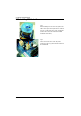
Driver Installation Revision Chapter History 4 Application Driver Installation A. NVDIA Chipset Driver Installation Insert the driver CD-title that came with your motherboard into your CD-ROM driver, the driver CD-title will auto start and show the installation guide. If not, please double click the CD-ROM device icon in "My computer", and execute the setup.exe. Installation Procedures: 1. The CD auto run program starts, Click on “nVDIA Chipset Driver” to start the installation. 2.
GA-3PXSL-RH Motherboard 2. InstallShield Wizard Welcome Window 2. Click "Next" to start the installation 3. Select Features 3. Select the feature setup that you want to install. And click "Next".
Driver Installation 4. NVDIA IDE SW Driver Information 4. Click "Next" to process the installation. 5. IDE SW Driver Installation Confirmation Dialog 5. Click “Yes”.
GA-3PXSL-RH Motherboard 6. Firewall and ForceWare Network Access Manager Installation Confirmation Dialog 6. Click “Yes”. 7. Network Access Manager Installation 7. Click “Next”.
Driver Installation 8. Network Access Manager Setup Type Selection 8. Select the setup type and determine the driver destination folder. Click “Next” 9. Network Access Manager Installation Language Preference 9. Select the language, and click “Next”.
GA-3PXSL-RH Motherboard 10. ActiveAmor FireWall Installation 11. Installation Complete. Restart Computer 10. Select ‘Yes, I want to restart my computer now’ and click “Finish”.
Driver Installation B. nVIDIA VGA Driver Installation Insert the driver CD-title that came with your motherboard into your CD-ROM driver, the driver CD-title will auto start and show the installation guide. If not, please double click the CD-ROM device icon in "My computer", and execute the setup.exe. Installation Procedures: 1. The CD auto run program starts, Click on “nVIDIA VGA Driver” to start the installation. 2. Then, a series of installation wizards appear.
GA-3PXSL-RH Motherboard 2. InstallShield Wizard Welcom Window 2. Click "Next" to start the installation 3. Installaiton Wizard Completed 3. Select ‘Yes, I want to restart my computer now’ and click “Finish”.
Driver Installation C. Marvell LAN Driver Installation Insert the driver CD-title that came with your motherboard into your CD-ROM driver, the driver CD-title will auto start and show the installation guide. If not, please double click the CD-ROM device icon in "My computer", and execute the setup.exe. Installation Procedures: 1. The CD auto run program starts, Click on “Marvell LAN Driver” to start the installation. 2. Then, a series of installation wizards appear.
GA-3PXSL-RH Motherboard 2. InstallShield Wizard Welcome Window 2. Click "Next" to start the installation 3. License Agreement 2. Select “I accept the terms in the license agreement andclick "Next" to process the installation.
Driver Installation 4. Ready to Install the Program 4. Click "Install" to start the installation 5. Installaiton Wizard Completed 4. Click "Finish".
GA-3PXSL-RH Motherboard D. DirectX 9.0 Driver Installation Insert the driver CD-title that came with your motherboard into your CD-ROM driver, the driver CD-title will auto start and show the installation guide. If not, please double click the CD-ROM device icon in "My computer", and execute the setup.exe. Installation Procedures: 1. The CD auto run program starts, Double click on “Directx9.0” to start the installation. 2. Then, a series of installation wizards appear.
Driver Installation 2. License Agreement 2. Select “I accept the agreement andclick "Next" to process the installation. 3. Start Installaiton 3. Click “Next” to start the installation .
GA-3PXSL-RH Motherboard 4. Installaiton Wizard completed 4. Click "Finish". Installation complete.
Appendix Revision Chapter History 5 Appendix Appendix : Acronyms Acronyms ACPI Meaning Advanced Configuration and Power Interface APM AGP Advanced Power Management Accelerated Graphics Port AMR ACR Audio Modem Riser Advanced Communications Riser BBS BIOS BIOS Boot Specification Basic Input / Output System CPU CMOS Central Processing Unit Complementary Metal Oxide Semiconductor CRIMM CNR Continuity RIMM Communication and Networking Riser DMA DMI Direct Memory Access Desktop Management Interface
GA-3PXSL-RH Motherboard Acronyms I/O Meaning Input / Output IOAPIC ISA Input Output Advanced Programmable Input Controller Industry Standard Architecture LAN LBA Local Area Network Logical Block Addressing LED MHz Light Emitting Diode Megahertz MIDI MTH Musical Instrument Digital Interface Memory Translator Hub MPT NIC Memory Protocol Translator Network Interface Card OS OEM Operating System Original Equipment Manufacturer PAC POST PCI A.G.P.