GA-M59SLI-S5 / GA-M59SLI-S4 AMD Socket AM2 Processor Motherboard User's Manual Rev. 1003 12ME-M59SLIS5-1003R * The WEEE marking on the product indicates this product must not be disposed of with user's other household waste and must be handed over to a designated collection point for the recycling of waste electrical and electronic equipment!! * The WEEE marking applies only in European Union's member states.
Motherboard GA-M59SLI-S5 / GA-M59SLI-S4 Jun. 8, 2006 Motherboard GA-M59SLI-S5 / GA-M59SLI-S4 Jun.
Copyright © 2006 GIGA-BYTE TECHNOLOGY CO., LTD. All rights reserved. The trademarks mentioned in the manual are legally registered to their respective companies. Notice The written content provided with this product is the property of Gigabyte. No part of this manual may be reproduced, copied, translated, or transmitted in any form or by any means without Gigabyte's prior written permission. Specifications and features are subject to change without prior notice.
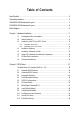
Table of Contents Item Checklist ................................................................................................................. 6 Optional Accessories ...................................................................................................... 6 GA-M59SLI-S5 Motherboard Layout ............................................................................. 7 GA-M59SLI-S4 Motherboard Layout .............................................................................
Chapter 3 Drivers Installation ...................................................................................... 61 3-1 Install Chipset Drivers .................................................................................... 61 3-2 3-3 Software Applications ..................................................................................... 62 Driver CD Information .................................................................................... 62 3-4 3-5 Hardware Information ............
Item Checklist IDE Cable x 1 & FDD Cable x 1 SATA 3Gb/s Cable x 4 eSATA adapter package x 1 I/O Shield SLI Bridge (GC-DGBR2-RH) x 1 Retention Bracket x 1 * The items listed above are for reference only, and are subject to change without notice. Optional Accessories 2 Ports USB2.0 Cable (Part Number: 12CR1-1UB030-51/R) 4 Ports USB2.0 Cable (Part Number: 12CR1-1UB030-21/R) 2 Ports IEEE1394 Cable (Part Number: 12CF1-1IE008-01R) Only for GA-M59SLI-S5.
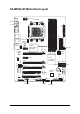
GA-M59SLI-S5 Motherboard Layout ATX_12V_2X KB_MS Socket AM2 OPTICAL R_1394 IDE1 Marvell 88E1116 CD_IN SPDIF_I PCIE_2 SYS_FAN FDD nVIDIA ® nForce 590SLI Southbridge PCIE_8 SATAII1 SATAII3 SATAII0 PCIE_16_2 IT8716 SATAII5 SATAII4 SATAII2 BAT PCI1 GIGABYTE SATA2 CLR_CMOS Main BIOS F_USB3 F_USB2 TSB43AB23 PCI2 CI TPM F2_1394 JSATAII1 F1_1394 JSATAII0 PCIE_12V -7- PWR_LED Backup BIOS F_PANEL F_USB1 CODEC PCIE_16_1 DDRII4 Marvell 88E1116 GA-M59SLI-S5 DDRII3 nForce 590SLI Nort
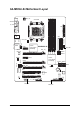
GA-M59SLI-S4 Motherboard Layout ATX_12V KB_MS Socket AM2 OPTICAL R_1394 USB COMA LPT ATX IDE1 CODEC PWR_FAN PCIE_2 nVIDIA ® nForce 590SLI Southbridge PCIE_8 SATAII5 SATAII4 SATAII1 SATAII3 SATAII0 PCIE_16_2 SATAII2 SB_FAN BAT PCI1 CLR_CMOS BIOS TSB43AB23 F_USB3 F_USB2 IT8716 SYS_FAN FDD PCI2 CI F_PANEL F2_1394 F1_1394 PCIE_12V PWR_LED -8- F_USB1 SPDIF_I CD_IN PCIE_16_1 DDRII4 Marvell 88E1116 GA-M59SLI-S4 DDRII3 nVIDIA® nForce 590SLI Northbridge PCIE_1 DDRII1 AUDIO D
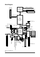
Block Diagram CPUCLK+/-(200MHz) PCI-ECLK (100MHz) AMD Socket AM2 CPU DDRII 800/667/533/400MHz DIMM Dual Channel Memory Hyper Transport Bus PCI Express x16 nVIDIA® nForce 590SLI Northbridge 2 SATA 3Gb/s GIGABYTE SATA2 2 PCI Express x1 Hyper Transport Bus PCI-ECLK (100MHz) Dual BIOS PCI Express x1 88E1116 x 2 Marvell RJ45 RJ45 LAN1 LAN2 6 SATA 3Gb/s nVIDIA® nForce 590SLI Southbridge ATA33/66/100/133 IDE Channel Floppy LPC BUS PCI Bus IT8716 LPT Port COM Port TSB43AB23 PS/2 KB/Mouse 2 PCI
- 10 -
1-1 English Chapter 1 Hardware Installation Considerations Prior to Installation Preparing Your Computer The motherboard contains numerous delicate electronic circuits and components which can become damaged as a result of electrostatic discharge (ESD). Thus, prior to installation, please follow the instructions below: 1. Please turn off the computer and unplug its power cord. 2. When handling the motherboard, avoid touching any metal leads or connectors. 3.
English 1-2 Feature Summary CPU Front Side Bus Chipset LAN Audio IEEE 1394 Storage O.
Rear Panel I/O I/O Control Hardware Monitor BIOS 1 24-pin ATX power connector 1 8-pin ATX 12V power connector 1 4-pin ATX 12V power connector 1 4-pin PCIE 12V power connector 1 floppy connector 1 IDE connector 8 SATA 3Gb/s connectors 6 SATA 3Gb/s connectors 1 CPU fan connector 1 system fan connector 1 power fan connector 1 SB fan connector 1 front panel connector 1 front audio connector 1 CD In connector 1 power LED connecto
English Additional Features Bundle Software Form Factor Supports @BIOS Supports Download Center Supports Q-Flash Supports EasyTune (Note 3) Supports Xpress Install Supports Xpress Recovery2 Supports Xpress BIOS Rescue Norton Internet Security (OEM version) ATX form factor; 30.5cm x 24.
Installation of the CPU and CPU Cooler Before installing the CPU, please comply with the following conditions: 1. Please make sure that the motherboard supports the CPU. 2. Please take note of the pin 1 marking (the small triangle) on the CPU. If you install the CPU in the wrong direction, the CPU will not insert properly. If this occurs, please change the insert direction of the CPU. 3. Please add an even layer of heat paste between the CPU and CPU cooler. 4.
English 1-3-2 Installation of the CPU Cooler Fig.1 Before installing the CPU cooler, please first add an even layer of heat paste on the surface of the CPU. Install all the CPU cooler components (Please refer to the cooler manual for detailed installation instructions). Fig.2 Please connect the CPU cooler power connector to the CPU_FAN connector located on the motherboard so that the CPU cooler can properly function to prevent CPU overheating.
Installation of Memory Before installing the memory modules, please comply with the following conditions: 1. Please make sure that the memory used is supported by the motherboard. It is recommended that memory of similar capacity, specifications and brand be used. 2. Before installing or removing memory modules, please make sure that the computer power is switched off to prevent hardware damage. 3. Memory modules have a foolproof insertion design. A memory module can be installed in only one direction.
English Dual Channel Memory Configuration The GA-M59SLI-S5/GA-M59SLI-S4 supports the Dual Channel Technology. After operating the Dual Channel Technology, the bandwidth of Memory Bus will double. Due to CPU limitation, if you wish to operate the Dual Channel Technology, follow the guidelines below: 1. Dual Channel mode will not be enabled if only one memory module is installed. 2.
Installation of Expansion Cards You can install your expansion card by following the steps outlined below: 1. Read the related expansion card's instruction document before install the expansion card into the computer. 2. Remove your computer's chassis cover, screws and slot bracket from the computer. 3. Press the expansion card firmly into expansion slot in motherboard. 4. Be sure the metal contacts on the card are indeed seated in the slot. 5.
English 1-6 Setup of SLI (Scalable Link Interface) Configuration nVIDIA nForce 590SLI offers blistering graphics performance with the ability to bridge two NVIDIA SLIready PCI ExpressTM graphics cards! The SLI design takes advantage of the increased bandwidth of the PCI Express TM bus architecture, features hardware and software innovations within NVIDIA GPU (graphics processing unit) and the nVIDIA® nForce 590SLI chipset.
English Connecting Two Graphics Cards: Step 1: Observe the steps in "1-5 Installation of Expansion Cards" and install two SLI-ready graphics cards of the same model to the PCIE_16_1 and PCIE_16_2 slots. Step 2: Insert the SLI bridge (the GC-DGBR2-RH) to the SLI gold edge connector on top of both cards. Make sure the two mini female slots on the bridge connector securely fit onto the SLI gold edge connetors of both cards.
English Graphics Card Driver Setting: Step 1: After installing graphics card driver in operating system, right-click the NVIDIA icon in your system tray and then select NVIDIA Display. The NVIDIA control panel will appear. Step 2: Select SLI multi-GPU from the side menu and then select the Enable SLI multi-GPU checkbox in the SLI multi-GPU dialog box. System will restart after you click Apply. Then the SLI configuration is completed.
I/O Back Panel Introduction English 1-7 PS/2 Keyboard and PS/2 Mouse Connector To install a PS/2 port keyboard and mouse, plug the mouse to the upper port (green) and the keyboard to the lower port (purple). Parallel Port The parallel port allows connection of a printer, scanner and other peripheral devices. IEEE 1394 Port (4 Pins Connector) Serial interface standard set by Institute of Electrical and Electronics Engineers, which has features like high speed, high bandwidth and hot plug.
English Line Out (Front Speaker Out) The default Line Out (Front Speaker Out) jack. Stereo speakers, earphone or front surround speakers can be connected to Line Out (Front Speaker Out) jack. MIC In The default MIC In jack. Microphone must be connected to MIC In jack. In addition to the default speakers settings, the ~ audio jacks can be reconfigured to perform different functions via the audio software. Only microphones still MUST be connected to the default Mic In jack ( ).
ATX_12V_2X / ATX_12V (Power Connector) ATX (Power Connector) With the use of the power connector, the power supply can supply enough stable power to all the components on the motherboard. Before connecting the power connector, please make sure that all components and devices are properly installed. Align the power connector with its proper location on the motherboard and connect tightly. The ATX_12V power connector mainly supplies power to the CPU.
English ATX (Power Connector) Pin No. 1 13 1 24 12 Definition 3.3V 2 3 3.3V GND 4 5 +5V GND 6 7 +5V GND 8 9 Power Good 5V SB(stand by +5V) 10 11 +12V +12V(Only for 24-pin ATX) 12 3.3V(Only for 24-pin ATX) GA-M59SLI-S5/GA-M59SLI-S4 Motherboard - 26 - Pin No. Definition 13 14 3.
The PCIE_12V power connector supplies extra power to the PCIE x16 slot. Connect this connector depending on your system requirements. PIin No. 1 4/5/6) Definition 1 2 NC GND 3 4 GND +12V CPU_FAN / SYS_FAN / PWR_FAN (Cooler Fan Power Connector) The cooler fan power connector supplies a +12V power voltage via a 3-pin/4-pin (only for CPU_FAN) power connector and possesses a foolproof connection design. Most coolers are designed with color-coded power connector wires.
English 7) SB_FAN (Chip Fan Connector) If you installed wrong direction, the chip fan will not work. Sometimes will damage the chip fan. (Usually black cable is GND) Pin No. 1 2 1 Definition +12V GND 8) IDE1 (IDE Connector) An IDE device connects to the computer via an IDE connector. One IDE connector can connect to one IDE cable, and the single IDE cable can then connect to two IDE devices (hard drive or optical drive).
The FDD connector is used to connect the FDD cable while the other end of the cable connects to the FDD drive. The types of FDD drives supported are: 360KB, 720KB, 1.2MB, 1.44MB and 2.88MB. Before attaching the FDD cable, please take note of the foolproof groove in the FDD connector.
The PWR_LED connector is connected with the system power indicator to indicate whether the system is on/off. It will blink when the system enters suspend mode. Pin No. 1 1 Definition MPD+ 2 3 MPDMPD- 13) F_PANEL (Front Panel Jumper) Please connect the power LED, PC speaker, reset switch and power switch etc of your chassis front panel to the F_PANEL connector according to the pin assignment below.
This connector supports either HD (High Definition) or AC97 front panel audio module. If you wish to use the front audio function, connect the front panel audio module to this connector. Check the pin assignments carefully while you connect the front panel audio module. Incorrect connection between the module and connector will make the audio device unable to work or even damage it. For optional front panel audio module, please contact your chassis manufacturer. 10 9 2 1 AC'97 Audio: Pin No.
English 15) CD_IN (CD In Connector) Connect CD-ROM or DVD-ROM audio out to the connector. Pin No. 1 1 Definition CD-L 2 3 GND GND 4 CD-R 16) SPDIF_I (SPDIF In) Use SPDIF IN feature only when your device has digital output function. Be careful with the polarity of the SPDIF_IN connector. Check the pin assignment carefully while you connect the SPDIF cable, incorrect connection between the cable and connector will make the device unable to work or even damage it.
Be careful with the polarity of the front USB connector. Check the pin assignment carefully while you connect the front USB cable, incorrect connection between the cable and connector will make the device unable to work or even damage it. For optional front USB cable, please contact your local dealer. 10 9 2 1 Pin No.
English 19) TPM Connector (Trusted Platform Module) Please contact your nearest dealer for optional TPM cable. Pin No. 2 20 1 19 Definition Pin No. Definition 1 2 LCLK GND 11 12 LAD0 GND 3 4 LFRAME No Pin 13 14 RSVO RSV1 5 6 LRESET VCC5 15 16 SB3V SERIRQ 7 8 LAD3 LAD2 17 18 GND CLKRUN 9 10 VCC3 LAD1 19 20 LPCPD RSV2 20) CLR_CMOS (Clear CMOS) You may clear the CMOS data to its default values by this header. To clear CMOS, temporarily short the two pins.
This 2-pin connector allows your system to detect if the chassis cover is removed. You can check the "Case Opened" status in BIOS Setup. Pin No. 1 1 2 Definition Signal GND 22) BATTERY Danger of explosion if battery is incorrectly replaced. Replace only with the same or equivalent type recommended by the manufacturer. Dispose of used batteries according to the manufacturer's instructions. If you want to erase CMOS... 1. Turn off the computer and unplug the power cord. 2.
English GA-M59SLI-S5/GA-M59SLI-S4 Motherboard - 36 -
BIOS (Basic Input and Output System) includes a CMOS SETUP utility which allows user to configure required settings or to activate certain system features. The CMOS SETUP saves the configuration in the CMOS SRAM of the motherboard. When the power is turned off, the battery on the motherboard supplies the necessary power to the CMOS SRAM. When the power is turned on, pressing the button during the BIOS POST (Power-On Self Test) will take you to the CMOS SETUP screen.
English : For Boot Menu Select boot sequence for onboard (or add-on cards) device. Boot Menu == Select a Boot First device == Award Modular BIOS v6.00PG, An Energy Star Ally Copyright (C) 1984-2006, Award Software, Inc. Floppy LS120 Hard Disk CDROM ZIP USB-FDD USB-ZIP USB-CDROM USB-HDD Legacy LAN GA-M59SLI-S5 F2 . . . .
English Standard CMOS Features This setup page includes all the items in standard compatible BIOS. Advanced BIOS Features This setup page includes all the items of Award special enhanced features. Integrated Peripherals This setup page includes all onboard peripherals. Power Management Setup This setup page includes all the items of Green function features. PnP/PCI Configuration This setup page includes all the configurations of PCI & PnP ISA resources.
English 2-1 Standard CMOS Features CMOS Setup Utility-Copyright (C) 1984-2006 Award Software Standard CMOS Features Date (mm:dd:yy) Time (hh:mm:ss) Tue, Mar 28 2006 14:42:37 Item Help Menu Level IDE Channel 0 Master IDE Channel 0 Slave IDE Channel 2 Master IDE Channel 3 Master IDE Channel 4 Master IDE Channel 5 Master IDE Channel 6 Master IDE Channel 7 Master [None] [None] [None] [None] [None] [None] [None] [None] Change the day, month, year Drive A Drive B Floppy 3 Mode Support [1.44M, 3.
The times format in . The time is calculated base on the 24-hour militarytime clock. For example, 1 p.m. is 13:00:00. IDE Channel 0 Master, Slave IDE HDD Auto-Detection Press "Enter" to select this option for automatic device detection. IDE Device Setup.
English Floppy 3 Mode Support (for Japan Area) Disabled Drive A Drive B Both Normal Floppy Drive. (Default value) Drive A is 3 mode Floppy Drive. Drive B is 3 mode Floppy Drive. Drive A & B are 3 mode Floppy Drives. Halt on The category determines whether the computer will stop if an error is detected during power up. No Errors The system boot will not stop for any error that may be detected and you will be prompted. All Errors Whenever the BIOS detects a non-fatal error the system will be stopped.
Advanced BIOS Features English 2-2 CMOS Setup Utility-Copyright (C) 1984-2006 Award Software Advanced BIOS Features Hard Disk Boot Priority First Boot Device Second Boot Device Third Boot Device Boot Up Floopy Seek Password Check Away Mode Init Display First : Move F11/12: Profile [Press Enter] [Floppy] [Hard Disk] [CDROM] [Disabled] [Setup] [Disabled] [PEG] Item Help Menu Level Select Hard Disk Boot Device Priority Enter: Select +/-/PU/PD: Value F10: Save ESC: Exit F1: General Help F5: Previous Valu
English Password Check System Setup The system can not boot and can not access to Setup page will be denied if the correct password is not entered at the prompt. The system will boot, but access to Setup will be denied if the correct password is not entered at the prompt. (Default value) Away Mode Disabled Enabled Disable this function. (Default value) Enable Away Mode in Windows XP Media Center operating system.
Integrated Peripherals English 2-3 CMOS Setup Utility-Copyright (C) 1984-2006 Award Software Integrated Peripherals Serial-ATA RAID Config On-Chip IDE Channel0 On-Chip MAC Lan On-Chip MAC1 Lan 1 NV Serial-ATA Controller IDE Prefetch Mode Onboard Audio Function SMART LAN Onboard 1394 Onboard LAN Boot ROM Onboard SATA/IDE Ctrl Mode 1 Onboard Serial Port 1 Onboard Parallel Port Parallel Port Mode x ECP Mode Use DMA On-Chip USB USB Keyboard Support USB Mouse Support Legacy USB Storage detect : Move F11/12: P
English NV SATA RAID function Enabled Disabled Enable NV SATA RAID function. Disable NV SATA RAID function. (Default value) NV SATA 1 Primary RAID Enabled Disabled Enable NV SATA 1 primary RAID function. Disable this function. (Default value) NV SATA 1 Secondary RAID Enabled Disabled Enable NV SATA 1 secondary RAID function. Disable this function. (Default value) NV SATA 2 Primary RAID Enabled Disabled Enable NV SATA 2 primary RAID function. Disable this function.
English SMART LAN (LAN Cable Diagnostic Function) CMOS Setup Utility-Copyright (C) 1984-2006 Award Software SMART LAN Start detecting Pair1-2 Status Pair3-6 Status Pair4-5 Status Pair7-8 Status at Port 0. = Normal = Normal = Normal = Normal / / / / Length Length Length Length = = = = N/A N/A N/A N/A Start detecting at Port 1.
English Onboard SATA/IDE Ctrl Mode RAID AHCI IDE Set the onboard SATA controller to RAID mode. Set the onboard SATA controller to AHCI mode. Advanced Host Controller Interface (AHCI) is an interface specification that allows the storage driver to enable advanced Serial ATA features such as Native Command Queuing and hot plug. For more details about AHCI, please visit Intel's website. Set the onboard SATA controller to IDE mode.
Power Management Setup English 2-4 CMOS Setup Utility-Copyright (C) 1984-2006 Award Software Power Management Setup ACPI Suspend Type Soft-Off by Power button PME Event Wake Up Modem Ring On USB Resume from Suspend Power-On by Alarm x Day of Month Alarm x Time (hh:mm:ss) Alarm Power On By Mouse Power On By Keyboard x KB Power ON Function AC BACK Function : Move F11/12: Profile [S1(POS)] [Instant-off] [Disabled] [Disabled] [Disabled] [Disabled] Everyday 0:0:0 [Disabled] [Disabled] Enter [Soft-Off] Item
English Power On By Mouse Disabled Double Click Disable this function. (Default value) Double click on PS/2 mouse left button to power on the system. Power On By Keyboard Disabled Password Any KEY Keyboard 98 Disable this function. (Default value) Enter from 1 to 5 characters to set the Keyboard Power On Password. Press any key to power on the system. If your keyboard have "POWER Key" button, you can press the key to power on the system.
PnP/PCI Configurations CMOS Setup Utility-Copyright (C) 1984-2006 Award Software PnP/PCI Configurations PCI 2 IRQ Assignment PCI 1 IRQ Assignment : Move F11/12: Profile [Auto] [Auto] Item Help Menu Level Enter: Select +/-/PU/PD: Value F10: Save ESC: Exit F1: General Help F5: Previous Values F6: Fail-Safe Defaults F7: Optimized Defaults PCI 2 IRQ Assignment Auto 3,4,5,7,9,10,11,12,14,15 Auto assign IRQ to PCI 2. (Default value) Set IRQ 3,4,5,7,9,10,11,12,14,15 to PCI 2.
English 2-6 PC Health Status CMOS Setup Utility-Copyright (C) 1984-2006 Award Software PC Health Status Reset Case Open Status Case Opened Vcore DDR18V +3.
Disabled Enabled Disable this function. When this function is enabled, CPU fan will run at different speed depending on CPU temperature. Users can adjust the fan speed with Easy Tune based on their requirements. (Default value) CPU Smart FAN Mode This option is available only when CPU Smart FAN Control is enabled. Auto BIOS autodetects the type of CPU fan you installed and sets the optimal CPU Smart FAN control mode for it.
English CPU Clock Ratio This setup option will automatically assign by CPU detection. The option will display "Locked" and read only or will not show up if the CPU ratio is not changeable. Robust Graphics Booster Select the options can enhance the VGA graphics card bandwidth to get higher performance. Auto Set Robust Graphics Booster to Auto. (Default value) Fast Set Robust Graphics Booster to Fast. Turbo Set Robust Graphics Booster to Turbo.
English N-Chipset/PCIE Voltage Set the voltage settings for Northbridge, its PCI Express bus voltage. Normal +0.1V +0.2V +0.3V Set Northbridge/PCIE voltage to Normal. (Default value) Set Northbridge/PCIE voltage to +0.1V. Set Northbridge/PCIE voltage to +0.2V. Set Northbridge/PCIE voltage to +0.3V. CPU Voltage Control Supports adjustable CPU Vcore from 0.800V to 1.550V. (Default value: Normal) Normal CPU Vcore Display your CPU Vcore voltage.
English 2-8 Load Fail-Safe Defaults CMOS Setup Utility-Copyright (C) 1984-2006 Award Software Standard CMOS Features Advanced BIOS Features Integrated Peripherals Power Management Setup PnP/PCI Configurations PC Health Status Load Fail-Safe Defaults Load Optimized Defaults Set Supervisor Password Set User Password Load Fail-Safe DefaultsSave (Y/N)? N Setup & Exit Exit Without Saving MB Intelligent Tweaker(M.I.T.
English 2-10 Set Supervisor/User Password CMOS Setup Utility-Copyright (C) 1984-2006 Award Software Standard CMOS Features Load Fail-Safe Defaults Advanced BIOS Features Load Optimized Defaults Set Supervisor Password Integrated Peripherals Set User Password Save & Exit Setup Power Management Setup Enter Password: PnP/PCI Configurations Exit Without Saving PC Health Status MB Intelligent Tweaker(M.I.T.
English 2-11 Save & Exit Setup CMOS Setup Utility-Copyright (C) 1984-2006 Award Software Standard CMOS Features Load Fail-Safe Defaults Advanced BIOS Features Load Optimized Defaults Set Supervisor Password Integrated Peripherals Power Management Setup PnP/PCI Configurations Set User Password Save to CMOS and EXIT (Y/N)? Y & Exit Setup Save Exit Without Saving PC Health Status MB Intelligent Tweaker(M.I.T.
English - 59 - BIOS Setup
English GA-M59SLI-S5/GA-M59SLI-S4 Motherboard - 60 -
Pictures below are shown in Windows XP. Insert the driver CD-title that came with your motherboard into your CD-ROM drive, the driver CD-title will auto start and show the installation guide. If not, please double click the CD-ROM device icon in "My computer", and execute the Run.exe. 3-1 Install Chipset Drivers After insert the driver CD, "Xpress Install" will scan automatically the system and then list all the drivers that recommended to install.
English 3-2 Software Applications This page displays all the tools that Gigabyte developed and some free software, you can choose anyone you want and press "install" to install them. 3-3 Driver CD Information This page lists the contents of software and drivers in this CD-title.
Hardware Information English 3-4 This page lists all device you have for this motherboard. 3-5 Contact Us Please see the last page for details.
English GA-M59SLI-S5/GA-M59SLI-S4 Motherboard - 64 -
4-1 English Chapter 4 Appendix Unique Software Utilities (Not all model support these Unique Software Utilities, please check your MB features.) 4-1-1 EasyTune 5 Introduction EasyTune 5 presents the most convenient Windows based system performance enhancement and manageability utility. Featuring several powerful yet easy to use tools such as 1) Overclocking for enhancing system performance, 2) C.I.A. and M.I.B.
English 4-1-2 Xpress Recovery2 Introduction Xpress Recovery2 is designed to provide quick backup and restoration of hard disk data. Supporting Microsoft operating systems including Windows XP/2000/NT/98/Me and DOS, and file systems including FAT16, FAT32, and NTFS, Xpress Recovery2 is able to back up data on hard disks on PATA and SATA IDE controllers. After Xpress Recovery2 is executed from CD-ROM for the first time, it will stay permanent in your hard disk.
1. RESTORE: Restore the backed-up data to your hard disk. (This button will not appear if there is no backup file.) 2. BACKUP: Back up data from hard disk. 3. REMOVE: Remove previously-created backup files to release disk space. (This button will not appear if there is no backup file.) 4. REBOOT: Exit the main screen and restart the system. Limitations: 1. 2. 3. Not compatible to Xpress Recovery. For the use of Xpress Recovery2, a primary partition must be reserved.
English 4-1-3 Flash BIOS Method Introduction A. What is Dual BIOS Technology ? Dual BIOS means that there are two system BIOS (ROM) on the motherboard, one is the Main BIOS and the other is Backup BIOS. Under the normal circumstances, the system works on the Main BIOS. If the Main BIOS is corrupted or damaged, the Backup BIOS can take over while the system is powered on. This means that your PC will still be able to run stably as if nothing has happened in your BIOS. B.
Dual BIOS Item explanation: Wide Range Protection: Disable(Default), Enable Status 1: If any failure (ex. Update ESCD failure, checksum error or reset? occurs in the Main BIOS, just before the Operating System is loaded and after the power is on, and that the Wide Range Protection is set to "Enable", the PC will boot from Backup BIOS automatically. Status 2: If the ROM BIOS on peripherals cards(ex. SCSI Cards, LAN Cards,..
English Method 1 : Q-FlashTM Utility Q-Flash TM is a BIOS flash utility embedded in Flash ROM. With this utility, users only have to stay in the BIOS menu when they want to update BIOS. Q-Flash?allows users to flash BIOS without any utility in DOS or Windows. Using Q-Flash TM indicating no more fooling around with any complicated instructions and operating system since it is in the BIOS menu.
English Entering the Q-FlashTM utility: Step1: To use Q-Flash utility, you must press Del in the boot screen to enter BIOS menu. CMOS Setup Utility-Copyright (C) 1984-2004 Award Software Standard CMOS Features Advanced BIOS Features Select Language Load Fail-Safe Defaults Integrated Peripherals Power Management Setup Load Optimized Defaults Set Supervisor Password PnP/PCI Configurations PC Health Status Set User Password Save & Exit Setup MB Intelligent Tweaker(M.I.T.
English Using the Q-FlashTM utility: This section tells you how to update BIOS using the Q-Flash utility. As described in the "Before you begin" section above, you must prepare a floppy disk having the BIOS file for your motherboard and insert it to your computer. If you have already put the floppy disk into your system and have entered the Q-Flash utility, please follow the steps below to flash BIOS. Steps: 1.
English 3. Press Y button on your keyboard after you are sure to update BIOS. Then it will begin to update BIOS. The progress of updating BIOS will be displayed. Please do not take out the floppy disk when it begins flashing BIOS. 4. Press any keys to return to the Q-Flash menu when the BIOS updating procedure is completed. Dual BIOS Utility Boot From......................................... Main Bios Main ROM Type/Size.............................SST 49LF004A Backup ROM Type/Size.........................
English 6. Press Del to enter BIOS menu after system reboots. When you are in BIOS menu, move to Load Optimized Defaults item and press Enter to load BIOS Optimized Defaults. Normally the system redetects all devices after BIOS has been upgraded. Therefore, we highly recommend reloading the BIOS defaults after BIOS has been upgraded.
The Q-FlashBIOS utility screen consists of the following key components. Q-Flash Utility V1.30 Flash Type/Size.................................SST 49LF003A Task menu for Q-FlashTM utility Enter : Run Keep DMI Data Enable Update BIOS from Floppy Save BIOS to Floppy :Move ESC:Reset Q-FlashTM utility bar 256K Action bar F10:Power Off Task menu for Q-Flash utility: Contains the names of three tasks. Blocking a task and pressing Enter key on your keyboard to enable execution of the task.
English 3. Press Y button on your keyboard after you are sure to update BIOS. Then it will begin to update BIOS. The progress of updating BIOS will be shown at the same time. Q-Flash Utility V1.30 Flash Type/Size.................................SST 49LF002A 256K Keep DMI Data BIOS Enable Updating Now Update BIOS from Floppy >>>>>>>>>>>>>>>>>>>......................... Save BIOS to Floppy EnterDon't : RunTurn Off Power :Move or Reset ESC:Reset F10:Power Off System 4.
If you do not have a DOS startup disk, we recommend that you use the new @BIOS utility. @BIOS allows users to update their BIOS under Windows. Just select the desired @BIOS server to download the latest version of BIOS. Fig 1. Installing the @BIOS utility Fig 2. Installation Complete and Run @BIOS Click Sart/ Programs/ GIGABYTE/@BIOS Select @BIOS item than click Install Fig 3. The @BIOS Utility Click " " Fig 4. Select the desired @BIOS server Click "Update New BIOS" 1. Methods and steps: I.
English III. Save BIOS In the very beginning, there is "Save Current BIOS" icon shown in dialog box. It means to save the current BIOS version. IV. Check out supported motherboard and Flash ROM: In the very beginning, there is "About this program" icon shown in dialog box. It can help you check out which kind of motherboard and which brand of Flash ROM are supported. 2. Note: I.
English 4-1-4 Configuring SATA Hard Drive(s) To configure SATA hard drive(s), follow the steps below: (1) Install SATA hard drive(s) in your system. (2) (3)* (4) (5) Configure SATA controller mode and boot sequence in BIOS Setup. Configure RAID set in RAID BIOS. Make a floppy disk containing the SATA controller driver. Install the SATA controller driver during OS installation.
English (2) Configuring SATA controller mode and boot sequence in BIOS Setup You have to make sure whether the SATA controller is configured correctly in system BIOS Setup and set BIOS boot sequence for the SATA hard drive(s)/RAID array. Step 1: Turn on your computer and press Del to enter BIOS Setup during POST (Power-On Self Test). In BIOS Setup, go to Integrated Periperals --> Serial-ATA RAID Config (Figure 1).
CMOS Setup Utility-Copyright (C) 1984-2006 Award Software Advanced BIOS Features Hard Disk Boot Priority First Boot Device Second Boot Device Third Boot Device Boot Up Floopy Seek Password Check Away Mode Init Display First : Move F11/12: Profile [Press Enter] [CDROM] [Hard Disk] [CDROM] [Disabled] [Setup] [Disabled] [PCI Slot] Item Help Menu Level Select Hard Disk Boot Device Priority Enter: Select +/-/PU/PD: Value F10: Save ESC: Exit F1: General Help F5: Previous Values F6: Fail-Safe Defaults F7: Opti
English (3) Configuring RAID set in RAID BIOS Enter the RAID BIOS setup utility to configure a RAID array. Skip this step and proceed to Section 4 if you do not want to create RAID. Step 1: After the POST memory test begins and before the operating system boot begins, look for a message which says "Press F10 to enter RAID setup utility" (Figure 4). Hit the F10 key to enter the RAID BIOS setup utility. MediaShield IDE ROM BIOS 6.55 Copyright (C) 2006 NVIDIA Corp. Detecting array ...
MediaShield Utility Mar 22 2006 - Define a New Array RAID Mode: Striping Free Disks Loc Disk Model Striping Block: Optimal Array Disks Loc Disk Model Capacity 1.0.M 2.1.M [ ] Add ST3120026AS ST3120026AS Capacity 111.78GB 111.78GB [ ] Del [ESC] Quit [F6] Back [F7] Finish [TAB] Navigate [ ] Select [ENTER] Popup Figure 6 Step 6: Press F7 after selecting the target hard disks. A message which says "Clear disk data?" will appear (Figure 7).
English After that, the Array List screen displaying the RAID array you created will appear (Figure 8). If you want to set the disk array as boot device, use the UP or DOWN ARROW key to select the array and press B. The Boot section will show Yes. MediaShield Utility Mar 22 2006 - Array List Boot Status Vendor Array Model Name BBS Healthy NVIDIA STRIPE 223.
To install operating system onto a serial ATA hard disk successfully, you need to install the SATA controller driver during OS installation. Without the driver, the hard disk may not be recognized during the Windows setup process. First of all, copy the driver for the SATA controller from the motherboard driver CD-ROM to a floppy disk. See the instructions below about how to copy the driver in MS-DOS mode (Note1). Prepare a startup disk that has CD-ROM support and a blank formatted floppy disk.
English (5) Installing SATA controller driver during OS installation Now that you have prepared the SATA driver disk and configured BIOS settings, you are ready to install Windows 2000/XP onto your SATA hard drive with the SATA driver. The following is an example of Windows XP installation. Step 1: Restart your system to boot from the Windows 2000/XP Setup disk and press F6 as soon as you see the "Press F6 if you need to install a 3rd party SCSI or RAID driver" message (Figure 13).
Windows Setup You have chosen to configure a SCSI Adapter for use with Windows, using a device support disk provided by an adapter manufacturer. Select the SCSI Adapter you want from the following list, or press ESC to return to the previous screen.
English Step 4: When the next screen (Figure 17) appears, press ENTER to continue the SATA driver installation from the floppy disk. Windows Setup Setup will load support for the following mass storage device(s): NVIDIA RAID CLASS DRIVER (required) NVIDIA nForce Storage Controller (required) * To specify additional SCSI adapters, CD-ROM drives, or special disk controllers for use with Windows, including those for which you have a device support disk from a mass storage device manufacturer, press S.
Problem: Users cannot install Windows 2000 with Service Pack 2 (or previous versions) to a bootable RAID volume. There are two solutions to resolve this issue. Solutions 1: Use the NVRAID tool (nForce Driver Version 5.xx) to convert the boot volume to a RAID array. Here are the detailed step-by-step instructions: Step 1: Install Windows 2000 onto a selected hard drive. Download and install Windows 2000 Service Pack 4 from Microsoft's website.
English Step 3: After system restarts, press F10 to enter the NVIDIA RAID setup utility. Select Striping in the RAID Mode filed (Figure 21). Move to the Free Disks section with the TAB key. Select the desired disk and use the RIGHT ARROW key to add it to Array Disks menu. MediaShield Utility Sep 21 2005 - Define a New Array RAID Mode: Striping Free Disks Loc Disk Model Striping Block: Optimal Array Disks Loc Disk Model Capacity 2.0.M 2.1.M [ ] Add ST3120026AS ST3120026AS Capacity 111.78G 111.
Solutions 2: Users must create a combination installation CD that includes Windows 2000 and Service Pack 3 or Service Pack 4 fixes integrated in. To create the combination installation CD, refer to the following website: http://www.microsoft.com/windows2000/downloads/servicepacks/sp4/HFdeploy.htm Note: If users choose not to install Windows 2000 Service Pack 3 or 4, RAID is still supported on Windows 2000. However, users will not be able to create a bootable RAID volume.
English B. GIGABYTE SATA2 Controller (1) Installing SATA hard drive(s) in your computer Attach one end of the SATA signal cable to the rear of the SATA hard drive and the other end to available SATA port(s) on the motherboard. If there are more than one SATA controller on your motherboard, you may refer to the motherboard user's manual to identify the SATA controller for the connector. Then connect the power connector from your power supply to the hard drive.
CMOS Setup Utility-Copyright (C) 1984-2006 Award Software Advanced BIOS Features Hard Disk Boot Priority First Boot Device Second Boot Device Third Boot Device Boot Up Floopy Seek Password Check Away Mode Init Display First : Move F11/12: Profile [Press Enter] [CDROM] [Hard Disk] [CDROM] [Disabled] [Setup] [Disabled] [PCI Slot] Item Help Menu Level Select Hard Disk Boot Device Priority Enter: Select +/-/PU/PD: Value F10: Save ESC: Exit F1: General Help F5: Previous Values F6: Fail-Safe Defaults F7: Opti
English (3) Configuring RAID array in RAID BIOS Enter the RAID BIOS setup utility to configure a RAID array. Skip this step if you do not want to create RAID. Step 1: After the POST memory test begins and before the operating system boot begins, look for a message which says "Press to enter RAID Setup Utility" (Figure 3). Press CTRL+ G to enter the GIGABYTE SATA2 RAID BIOS setup utility. GIGA-BYTE Technology Corp. PCIE-to-SATAII/IDE RAID Controller BIOS v1.06.
In the main screen, press ENTER on the Create RAID Disk Drive item. Then the RAID creation screen appears (Figure 5). GIGA-BYTE Technology Corp. PCIE-to-SATAII/IDE RAID Controller BIOS V1.06.
English 3. Assign Array Disks: After RAID mode is selected, RAID BIOS automatically assigns the two hard disks installed as the RAID disks. 4. Set Block Size (only for RAID 0): Under the Block item, use the UP or DOWN ARROW key to select the block size (Figure 7), ranging from 4K to 128K. Press ENTER when finished. GIGA-BYTE Technology Corp. PCIE-to-SATAII/IDE RAID Controller BIOS V1.06.
GIGA-BYTE Technology Corp. PCIE-to-SATAII/IDE RAID Controller BIOS V1.06.
English To check more detailed information about the array, use the TAB key while in the Main Menu block to move the selection bar to the RAID Disk Drive List block. Select the array and press ENTER. A small window displaying the array information will appear in the center of the screen (Figure 11). GIGA-BYTE Technology Corp. PCIE-to-SATAII/IDE RAID Controller BIOS V1.06.
To delete the array, select Delete RAID Disk Drive in the main menu and press ENTER. The selection bar will move to the RAID Disk Drive List block. Press the SPACEBAR on the array to be deleted; a small triangle will appear to mark the selected array (Figure 13). Press Del. GIGA-BYTE Technology Corp. PCIE-to-SATAII/IDE RAID Controller BIOS V1.06.
English (4) Making a SATA Driver Disk (Required for AHCI and RAID Mode) To install operating system onto a serial ATA hard disk successfully, you need to install the SATA controller driver during OS installation. Without the driver, the hard disk may not be recognized during the Windows setup process. First of all, copy the driver for the SATA controller from the motherboard driver CD-ROM to a floppy disk. See the instructions below about how to copy the driver in MS-DOS mode (Note1).
Now that you have prepared the SATA driver disk and configured BIOS settings, you are ready to install Windows 2000/XP onto your SATA hard drive with the SATA driver. The following is an example of Windows XP installation. Step 1: Restart your system to boot from the Windows 2000/XP Setup disk and press F6 as soon as you see the "Press F6 if you need to install a 3rd party SCSI or RAID driver" message (Figure 18).
English Step 3: If Setup correctly recognizes the driver in the floppy disk, a controller menu similar to Figure 20 below will appear. Use the ARROW keys to select GIGABYTE GBB363 RAID Controller(Windows 2K/XP/2003)* and press ENTER.Then it will begin to load the SATA driver from the floppy disk. Windows Setup You have chosen to configure a SCSI Adapter for use with Windows, using a device support disk provided by an adapter manufacturer.
WindowsXP Professional Setup Welcome to Setup. This port of the Setup program prepares Microsoft(R) Windows (R) XP to run on your computer. To set up Windows XP now, press ENTER. To repair a Windows XP installation using Recovery Console, press R. To quit Setup without installing Windows XP, press F3. Enter= Continue R=Repair F3=Exit Figure 22 - 103 - Appendix English Step 5: After the SATA controller driver installation is completed, you can proceed with the Windows XP installation.
English 4-1-5 2- / 4- / 6- / 8- Channel Audio Function Introduction A. Realtek ALC888DD CODEC The default speaker settings for the 6 audio jacks are as shown in the picture to the right. The jack retasking capability supported by HD Audio allows users to change the function for each audio jack by the audio software provided.
English STEP 2: In the Audio Control Panel, click the Audio I/O tab. In the upper left list, click 2CH Speaker. STEP 3: After a speaker or headphone is plugged into the rear Line Out jack, a small window will pop up and ask you what type of equipment is connected. Choose Headphone or Line Out depending on the device connected and click OK. The 2-channel audio setup is completed.
English STEP 3: After plugging in 4-channel speakers to the rear speaker jacks, a small window will pop up and ask you what type of equipment is connected. Choose a device depending on the type of speaker connected (4-channel audio consists of Front Speaker Out (Line Out) and Rear Speaker Out) and then click OK. The 4-channel audio setup is completed.
English 8 Channel Audio Setup STEP 1 : After installation of the audio driver, you should find an Audio Manager icon in your system tray (you can also find the icon in Control Panel). Doubleclick the icon to open the Audio Control Panel. STEP 2: In the Audio Control Panel, click the Audio I/O tab. In the upper left list, click 8CH Speaker. STEP 3: After plugging in 8-channel speakers to the rear speaker jacks, a small window will pop up and ask you what type of equipment is connected.
English Sound Effect Configuration: At the Sound Effect menu, users can adjust sound option settings as desired. AC'97 Audio Configuration: To enable the front panel audio connector to support AC97 Audio mode, go to the Audio Control Panel and click the Audio I/O tab. In the ANALOG area, click the Tool icon and then select the Disable front panel jack detection check box. This action completes the AC'97 Audio configuration.
Before DTS is enabled, you would get only 2-channel output signals (from the front speakers) when playing 2-channel music. You must play 4-, 6-, or 8channel music sources to produce 4-, 6-, or 8- channel audio effects. With DTS enabled, the system will transform two-channel stereo source material into multi-channel audio output, creating a virtual surround sound environment.
English Introduction of Dolby Digital Live: A real-time encoding technology, Dolby Digital Live converts any audio signal into a Dolby Digital bitstream for transport and playback through a home theater system. With it, your PC or game console can be hooked up to your Dolby Digital-equipped audio/video receiver or digital speaker system via a single digital connection, eliminating the confusion of multiple cables and ensuring the integrity of the audio signal.
The default speaker settings for the 6 audio jacks are as shown in the picture to the right. The jack retasking capability supported by HD Audio allows users to change the function for each audio jack by the audio software provided. For example, if a rear speaker is plugged into the center/subwoofer speaker out jack, you can change the center/ subwoofer speaker out jack to fucntion as a rear speaker out jack via the audio software.Please follow the steps to install the function.
English STEP 2: In the Audio Control Panel, click the Audio I/O tab. In the upper left list, click 2CH Speaker. STEP 3: After a speaker or headphone is plugged into the rear Line Out jack, a small window will pop up and ask you what type of equipment is connected. Choose Headphone or Line Out depending on the device connected and click OK. The 2-channel audio setup is completed.
English STEP 3: After plugging in 4-channel speakers to the rear speaker jacks, a small window will pop up and ask you what type of equipment is connected. Choose a device depending on the type of speaker connected (4-channel audio consists of Front Speaker Out (Line Out) and Rear Speaker Out) and then click OK. The 4-channel audio setup is completed.
English 8 Channel Audio Setup STEP 1 : After installation of the audio driver, you should find an Audio Manager icon in your system tray (you can also find the icon in Control Panel). Doubleclick the icon to open the Audio Control Panel. STEP 2: In the Audio Control Panel, click the Audio I/O tab. In the upper left list, click 8CH Speaker. STEP 3: After plugging in 8-channel speakers to the rear speaker jacks, a small window will pop up and ask you what type of equipment is connected.
English Sound Effect Configuration: At the Sound Effect menu, users can adjust sound option settings as desired. AC'97 Audio Configuration: To enable the front panel audio connector to support AC97 Audio mode, go to the Audio Control Panel and click the Audio I/O tab. In the ANALOG area, click the Tool icon and then select the Disable front panel jack detection check box. This action completes the AC'97 Audio configuration.
English 4-2 Troubleshooting Below is a collection of general asked questions. To check general asked questions based on a specific motherboard model, please log on to GIGABYTE's website. Question 1: I cannot see some options that were included in previous BIOS after updating BIOS. Why? Answer: Some advanced options are hidden in new BIOS version. Please press Ctrl and F1 keys after entering BIOS menu and you will be able to see these options.
English - 117 - Appendix
English Contact Us y Taiwan (Headquarters) GIGA-BYTE TECHNOLOGY CO., LTD. y China NINGBO G.B.T. TECH. TRADING CO., LTD. Address: No.6, Bau Chiang Road, Hsin-Tien, Taipei 231, Taiwan WEB address : http://www.gigabyte.cn Shanghai TEL: +886-2-8912-4888 FAX: +886-2-8912-4003 TEL: +86-21-63410999 FAX: +86-21-63410100 Tech. and Non-Tech. Support (Sales/Marketing) : http://ggts.gigabyte.com.tw Beijing TEL: +86-10-62102838 WEB address (English): http://www.gigabyte.com.tw WEB address (Chinese): http://www.
y Russia Moscow Representative Office Of GIGA-BYTE Technology Co., Ltd. WEB address : http://www.gigabyte.ru y Latvia G.B.T. TECH. CO., LTD. WEB address : http://www.giga-byte.co.uk y The Netherlands GIGA-BYTE Latvia WEB address : http://www.gigabyte.com.lv y Poland GIGA-BYTE TECHNOLOGY B.V. WEB address : http://www.giga-byte.nl y France Office of GIGA-BYTE TECHNOLOGY Co., Ltd. in POLAND GIGABYTE TECHNOLOGY FRANCE WEB address : http://www.gigabyte.pl y Ukraine WEB address : http://www.gigabyte.
- 120 -