B450 I AORUS PRO WIFI User's Manual Rev. 1001 12ME-B45IAPW-1001R For more product details, please visit GIGABYTE's website. To reduce the impacts on global warming, the packaging materials of this product are recyclable and reusable. GIGABYTE works with you to protect the environment.
Motherboard B450 I AORUS PRO WIFI Motherboard B450 I AORUS PRO WIFI Jul. 21, 2018 Jul.
Copyright © 2018 GIGA-BYTE TECHNOLOGY CO., LTD. All rights reserved. The trademarks mentioned in this manual are legally registered to their respective owners. Disclaimer Information in this manual is protected by copyright laws and is the property of GIGABYTE. Changes to the specifications and features in this manual may be made by GIGABYTE without prior notice.
Table of Contents B450 I AORUS PRO WIFI Motherboard Layout...............................................................5 Chapter 1 Hardware Installation......................................................................................6 1-1 1-2 1-3 1-4 1-5 1-6 1-7 Installation Precautions..................................................................................... 6 Product Specifications.......................................................................................
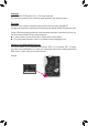
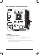
DP HDMI ATX_12V CPU_FAN ATX 42 (Note 2) AMD B450 PCIEX16 CODEC TPM SPEAKER F_USB1 F_USB30 60 SYS_FAN1 80 M_BIOS SPDIF_O F_AUDIO M2_WIFI iTE® Super I/O CI M2P D_LED LED_CPU CLR_CMOS USB30_LAN AUDIO SATA3 0 2 1 3 BAT F_PANEL HDMI 1 R_USB30 B450 I AORUS PRO WIFI Socket AM4 R_USB31 Intel® GbE LAN (Note 1) DDR4_1 DDR4_2 B450 I AORUS PRO WIFI Motherboard Layout Box Contents 55 55 55 55 B450 I AORUS PRO WIFI motherboard Motherboard driver disk User's Manual Two SATA cables 55 I/
Chapter 1 1-1 Hardware Installation Installation Precautions The motherboard contains numerous delicate electronic circuits and components which can become damaged as a result of electrostatic discharge (ESD). Prior to installation, carefully read the user's manual and follow these procedures: •• Prior to installation, make sure the chassis is suitable for the motherboard. •• Prior to installation, do not remove or break motherboard S/N (Serial Number) sticker or warranty sticker provided by your dealer.
1-2 Product Specifications CPU AM4 Socket: - AMD Ryzen™ 2nd Generation processors - AMD Ryzen™ with Radeon™ Vega Graphics processors - AMD Ryzen™ 1st Generation processors (Go to GIGABYTE's website for the latest CPU support list.
USB Internal Connectors Back Panel Connectors Chipset: - 2 x USB 3.1 Gen 2 Type-A ports (red) on the back panel - 2 x USB 3.1 Gen 1 ports available through the internal USB header - 2 x USB 2.0/1.1 ports available through the internal USB header Integrated in the APU: - 4 x USB 3.
Unique Features Support for APP Center * Available applications in APP Center may vary by motherboard model. Supported functions of each application may also vary depending on motherboard specifications.
1-3 Installing the CPU Read the following guidelines before you begin to install the CPU: •• Make sure that the motherboard supports the CPU. (Go to GIGABYTE's website for the latest CPU support list.) •• Always turn off the computer and unplug the power cord from the power outlet before installing the CPU to prevent hardware damage. •• Locate the pin one of the CPU. The CPU cannot be inserted if oriented incorrectly. •• Apply an even and thin layer of thermal grease on the surface of the CPU.
Due to CPU limitations, read the following guidelines before installing the memory in Dual Channel mode. 1. Dual Channel mode cannot be enabled if only one memory module is installed. 2. When enabling Dual Channel mode with two memory modules, it is recommended that memory of the same capacity, brand, speed, and chips be used. 1-5 Installing an Expansion Card Read the following guidelines before you begin to install an expansion card: •• Make sure the motherboard supports the expansion card.
RJ-45 LAN Port The Gigabit Ethernet LAN port provides Internet connection at up to 1 Gbps data rate. The following describes the states of the LAN port LEDs.
1-7 Internal Connectors 1 3 8 9 2 12 7 18 5 16 17 15 14 4 10 13 11 6 1) ATX_12V 10) F_AUDIO 2) ATX 11) SPDIF_O 3) CPU_FAN 12) SPEAKER 4) SYS_FAN1 13) TPM 5) D_LED 14) F_USB30 6) LED_CPU 15) F_USB1 7) SATA3 0/1/2/3 16) CI 8) M2P 17) CLR_CMOS 9) F_PANEL 18) BAT Read the following guidelines before connecting external devices: •• First make sure your devices are compliant with the connectors you wish to connect.
1/2) ATX_12V/ATX (2x4 12V Power Connector and 2x12 Main Power Connector) With the use of the power connector, the power supply can supply enough stable power to all the components on the motherboard. Before connecting the power connector, first make sure the power supply is turned off and all devices are properly installed. The power connector possesses a foolproof design. Connect the power supply cable to the power connector in the correct orientation.
3 _ _B S F_ 5) D_LED (Digital LED Strip Header) _ The header can be used to connect a standard 5050 digital LED strip, with maximum power rating of 2A (5V) and maximum length of 5m or maximum number of 300 LEDs. _ S 1 S_ _ B Digital LED Strip _ U _ B F_USB3 F Pin No. 1 2 3 4 1 G.QBOFM Definition V (5V) D No Pin G Connect your digital LED strip to the header. There are 12V and 5V digital LED strips. Be sure to verify the voltage requirements of your digital LED strips.
DEBUG PORT S S U 7) SATA3 0/1/2/3 (SATA 6Gb/s Connectors) 1 2 3 4 5 The SATA connectors conform to SATA 6Gb/s standard and are compatible with SATA 3Gb/s and SATA 1.5Gb/s standard. Each SATA connector supports a single SATA device. The SATA connectors support RAID 0, RAID 1, and RAID 10. Refer to Chapter 3, "Configuring a RAID Set," for instructions on configuring a RAID array. 1 7 Pin No. 1 2 3 4 5 6 7 SATA3 2 3 0 1 7 B S_ B 1 Definition GND TXP TXN GND RXN RXP GND 8) M2P (M.
9) F_PANEL (Front Panel Header) Connect the power switch, reset switch, and system status indicator on the chassis to this header according to the pin assignments below. Note the positive and negative pins before connecting the cables. 10 9 Power Switch Power LED PW- PW+ PLEDPLED+ 2 1 NC RES+ RESHDHD+ Reset Switch Hard Drive Activity LED •• PLED (Power LED, Yellow): Connects to the power status indicator on the chassis front panel. The LED System Status LED is on when the system is operating.
_ _B _ F S _ _ S 11) SPDIF_O (S/PDIF Out Header) S This header supports digital S/PDIF Out and connects a S/PDIF digital audio cable (provided by expansion cards) for digital audio output from your motherboard to certain expansion cards like graphics cards and sound cards.
F_USB30 F_ U F_ F_ 14) F_USB30 (USB 3.1 Gen 1 Header) The header conforms to USB 3.1 Gen 1 and USB 2.0 specification and can provide two USB ports. For purchasing the optional 3.5" front panel that provides two USB 3.1 Gen 1 ports, please contact the local dealer. 10 Definition VBUS SSRX1SSRX1+ GND SSTX1SSTX1+ GND Pin No. 8 9 10 B 11 12 13 14 Definition D1D1+ NC SS D2+ D2GND SSTX2+ Pin No. 15 16 17 18 19 20 _S 1 11 Pin No.
17) CLR_CMOS (Clear CMOS Jumper) Use this jumper to clear the BIOS configuration and reset the CMOS values to factory defaults. To clear the CMOS values, use a metal object like a screwdriver to touch the two pins for a few seconds. Open: Normal Short: Clear CMOS Values •• Always turn off your computer and unplug the power cord from the power outlet before clearing the CMOS values.
Chapter 2 BIOS Setup BIOS (Basic Input and Output System) records hardware parameters of the system in the CMOS on the motherboard. Its major functions include conducting the Power-On Self-Test (POST) during system startup, saving system parameters and loading operating system, etc. BIOS includes a BIOS Setup program that allows the user to modify basic system configuration settings or to activate certain system features.
2-2 The Main Menu System Time Setup Menus Hardware Information Configuration Items Current Settings Quick Access Bar allows you to enter Easy Mode, select BIOS default language, configure fan settings, or enter Q-Flash.
2-3 M.I.T. Whether the system will work stably with the overclock/overvoltage settings you made is dependent on your overall system configurations. Incorrectly doing overclock/overvoltage may result in damage to CPU, chipset, or memory and reduce the useful life of these components. This page is for advanced users only and we recommend you not to alter the default settings to prevent system instability or other unexpected results. (Inadequately altering the settings may result in system's failure to boot.
&& Core Performance Boost (Note 1) Allows you to determine whether to enable the Core Performance Boost (CPB) technology, a CPU performance-boost technology. (Default: Auto) && AMD Cool&Quiet function Enabled Lets the AMD Cool'n'Quiet driver dynamically adjust the CPU clock and VID to reduce heat output from your computer and its power consumption. (Default) Disabled Disables this function.
&& Memory Timing Mode Manual allows the memory timing settings below to be configurable. Options are: Auto (default), Manual. && Profile DDR Voltage When using a non-XMP memory module or Extreme Memory Profile (X.M.P.) is set to Disabled, the value is displayed according to your memory specification. When Extreme Memory Profile (X.M.P.) is set to Profile1 or Profile2, the value is displayed according to the SPD data on the XMP memory.
&& Fan Speed Control Allows you to determine whether to enable the fan speed control function and adjust the fan speed. Normal Allows the fan to run at different speeds according to the temperature. You can adjust the fan speed with System Information Viewer based on your system requirements. (Default) Silent Allows the fan to run at slow speeds. Manual Allows you to control the fan speed in the curve graph. Full Speed Allows the fan to run at full speeds.
2-4 System This section provides information on your motherboard model and BIOS version. You can also select the default language used by the BIOS and manually set the system time. && System Language Selects the default language used by the BIOS. && System Date Sets the system date. The date format is week (read-only), month, date, and year. Use to switch between the Month, Date, and Year fields and use the or key to set the desired value.
2-5 BIOS && Boot Option Priorities Specifies the overall boot order from the available devices. Removable storage devices that support GPT format will be prefixed with "UEFI:" string on the boot device list. To boot from an operating system that supports GPT partitioning, select the device prefixed with "UEFI:" string.
&& SATA Support Last Boot HDD Only Except for the previous boot drive, all SATA devices are disabled before the OS boot process completes. (Default) All Sata Devices All SATA devices are functional in the operating system and during the POST. This item is configurable only when Fast Boot is set to Enabled or Ultra Fast. && VGA Support Allows you to select which type of operating system to boot. Auto Enables legacy option ROM only. EFI Driver Enables EFI option ROM.
&& Network Stack Disables or enables booting from the network to install a GPT format OS, such as installing the OS from the Windows Deployment Services server. (Default: Disabled) && Ipv4 PXE Support Enables or disables IPv4 PXE Support. This item is configurable only when Network Stack is enabled. && Ipv4 HTTP Support Enables or disables HTTP boot support for IPv4. This item is configurable only when Network Stack is enabled. && Ipv6 PXE Support Enables or disables IPv6 PXE Support.
2-6 Peripherals && AMD CPU fTPM Enables or disables the TPM 2.0 function integrated in the AMD CPU. (Default: Disabled) && Initial Display Output Specifies the first initiation of the monitor display from the installed PCI Express graphics card or the onboard graphics. IGD Video (Note) Sets the onboard graphics as the first display. PCIe 1 Slot Sets the graphics card on the PCIEX16 slot as the first display. (Default) && Legacy USB Support Allows USB keyboard/mouse to be used in MS-DOS.
&& RGB Fusion Allows you to set the LED lighting mode for the motherboard. Off Disables this function. Pulse Mode All LEDs simultaneously fade in and fade out. Color Cycle All LEDs simultaneously cycle through a full spectrum of colors. Static Mode All LEDs emit a single color. (Default) Flash Mode All LEDs simultaneously flash on and off. Double Flash All LEDs flash in an interlaced pattern.
2-7 Chipset && IOMMU Enables or disables AMD IOMMU support. (Default: Auto) && Integrated Graphics (Note) Enables or disables the onboard graphics function. Auto The BIOS will automatically enable or disable the onboard graphics depending on the graphics card being installed. (Default) Forces Enables the onboard graphics. Disabled Disables the onboard graphics. && UMA Mode (Note) Specify the UMA mode. Auto Lets the BIOS automatically configure this setting.
&& SATA Mode Enables or disables RAID for the SATA controllers integrated in the Chipset or configures the SATA controllers to AHCI mode. RAID Enables RAID for the SATA controller. AHCI Configures the SATA controllers to AHCI mode. Advanced Host Controller Interface (AHCI) is an interface specification that allows the storage driver to enable advanced Serial ATA features such as Native Command Queuing and hot plug. (Default) && NVMe RAID mode Allows you to determine whether to use your M.
2-8 Power && AC BACK Determines the state of the system after the return of power from an AC power loss. Memory The system returns to its last known awake state upon the return of the AC power. Always On The system is turned on upon the return of the AC power. Always Off The system stays off upon the return of the AC power. (Default) && ErP Determines whether to let the system consume least power in S5 (shutdown) state.
&& Wake on LAN Enables or disables the wake on LAN function. (Default: Enabled) && High Precision Event Timer Enables or disables High Precision Event Timer (HPET) in the operating system. (Default: Enabled) && CEC 2019 Ready Allows you to select whether to allow the system to adjust power consumption when it is in shutdown, idle, or standby state in order to comply with the CEC (California Energy Commission) 2019 Standards.
2-9 Save & Exit && Save & Exit Setup Press on this item and select Yes. This saves the changes to the CMOS and exits the BIOS Setup program. Select No or press to return to the BIOS Setup Main Menu. && Exit Without Saving Press on this item and select Yes. This exits the BIOS Setup without saving the changes made in BIOS Setup to the CMOS. Select No or press to return to the BIOS Setup Main Menu.
Chapter 3 3-1 Appendix Configuring a RAID Set RAID Levels Minimum Number of Hard Drives Array Capacity Fault Tolerance RAID 0 ≥2 Number of hard drives * Size of the smallest drive No RAID 1 2 RAID 10 4 Size of the smallest drive (Number of hard drives/2) * Size of the smallest drive Yes Yes Before you begin, please prepare the following items: •• At least two SATA hard drives or SSDs. (To ensure optimal performance, it is recommended that you use two hard drives with identical model and capacity).
5. After setting the capacity, move to Create Array and press to begin. 6. After completing, you'll be brought back to the Array Management screen. Under Manage Array Properties you can see the new RAID volume and information on RAID level, array name, array capacity, etc. C-2. Configuring Legacy RAID ROM Enter the legacy RAID BIOS setup utility to configure a RAID array. Skip this step and proceed with the installation of Windows operating system for a non-RAID configuration. Steps: 1.
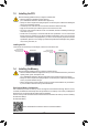
3-2 Drivers Installation •• Before installing the drivers, first install the operating system. •• After installing the operating system, insert the motherboard driver disk into your optical drive. Click on the message "Tap to choose what happens with this disc" on the top-right corner of the screen and select "Run Run.exe." (Or go to My Computer, double-click the optical drive and execute the Run.exe program.
Regulatory Statements Regulatory Notices This document must not be copied without our written permission, and the contents there of must not be imparted to a third party nor be used for any unauthorized purpose. Contravention will be prosecuted. We believe that the information contained herein was accurate in all respects at the time of printing. GIGABYTE cannot, however, assume any responsibility for errors or omissions in this text.
FCC Notice (U.S.A. Only) Operation is subject to the following two conditions: (1) this device may not cause harmful interference, and (2) this device must accept any interference received, including interference that may cause undesired operation. WARNING: This equipment has been tested and found to comply with the limits for a Class B digital device, pursuant to Part 15 of the FCC Rules. These limits are designed to provide reasonable protection against harmful interference in a residential installation.
Canada-Industry Canada (IC): This device complies with Canadian RSS-210. This device complies with Industry Canada license-exempt RSS standard(s). Operation is subject to the following two conditions: (1) this device may not cause interference, and (2) this device must accept any interference, including interference that may cause undesired operation of the device. Ce dispositif est conforme à la norme CNR-210 d'Industrie Canada applicable aux appareils radio exempts de licence.
European Community Radio Equipment Directive (RED) Compliance Statement: This equipment complies with all the requirements and other relevant provisions of Radio Equipment Directive 2014/53/EU. This equipment is suitable for home and office use in all the European Community Member States and EFTA Member States. The low band 5.15 -5.35 GHz is for indoor use only. Restrictions d'utilisation en France: Pour la France métropolitaine 2.400 - 2.4835 GHz (Canaux 1à 13) autorisé en usage intérieur 2.400 - 2.
- 45 -
- 46 -
- 47 -
Contact Us GIGA-BYTE TECHNOLOGY CO., LTD. Address: No.6, Baoqiang Rd., Xindian Dist., New Taipei City 231, Taiwan TEL: +886-2-8912-4000, FAX: +886-2-8912-4005 Tech. and Non-Tech. Support (Sales/Marketing) : https://esupport.gigabyte.com WEB address (English): https://www.gigabyte.com WEB address (Chinese): https://www.gigabyte.com/tw •• GIGABYTE eSupport To submit a technical or non-technical (Sales/Marketing) question, please link to: https://esupport.gigabyte.