B450M DS3H V2 User's Manual Rev. 1001 For more product details, please visit GIGABYTE's website. To reduce the impacts on global warming, the packaging materials of this product are recyclable and reusable. GIGABYTE works with you to protect the environment.
Copyright © 2020 GIGA-BYTE TECHNOLOGY CO., LTD. All rights reserved. The trademarks mentioned in this manual are legally registered to their respective owners. Disclaimer Information in this manual is protected by copyright laws and is the property of GIGABYTE. Changes to the specifications and features in this manual may be made by GIGABYTE without prior notice.
Table of Contents B450M DS3H V2 Motherboard Layout.............................................................................4 Chapter 1 Hardware Installation......................................................................................5 1-1 1-2 1-3 1-4 1-5 1-6 1-7 Installation Precautions..................................................................................... 5 Product Specifications.......................................................................................
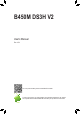
B450M DS3H V2 Motherboard Layout CPU_FAN ATX_12V KB_MS_USB DVI ATX Socket AM4 HDMI R_USB30_1 R_USB30_2 SYS_FAN1 USB_LAN 60 PCIEX16 CODEC B450M DS3H V2 SATA3 3 PCIEX1 AMD B450 BAT iTE® Super I/O PCIEX4 CLR_CMOS SATA3 0 1 2 Realtek® GbE LAN 42 DDR4_1 80 DDR4_2 M2A_SOCKET 110 DDR4_3 M_BIOS DDR4_4 LED_CPU AUDIO SPDIF_O F_AUDIO Box Contents TPM COM 55 B450M DS3H V2 Motherboard 55 Motherboard driver disc 55 User's Manual F_USB2 F_USB1 F_USB30 F_PANEL 55 Two SATA cables 55 I/O Shi
Chapter 1 1-1 Hardware Installation Installation Precautions The motherboard contains numerous delicate electronic circuits and components which can become damaged as a result of electrostatic discharge (ESD). Prior to installation, carefully read the user's manual and follow these procedures: •• Prior to installation, make sure the chassis is suitable for the motherboard. •• Prior to installation, do not remove or break motherboard S/N (Serial Number) sticker or warranty sticker provided by your dealer.
1-2 Product Specifications CPU AM4 Socket: - AMD 3rd Generation Ryzen™ processors - AMD 2nd Generation Ryzen™ processors - AMD 1st Generation Ryzen™ processors - AMD 2nd Generation Ryzen™ with Radeon™ Vega Graphics processors - AMD 1st Generation Ryzen™ with Radeon™ Vega Graphics processors - AMD Athlon™ with Radeon™ Vega Graphics processors (Go to GIGABYTE's website for the latest CPU support list.
Storage Interface 1 x M.2 connector (Socket 3, M key, type 2242/2260/2280/22110 SATA and PCIe 3.0 x4/x2 SSD support) 4 x SATA 6Gb/s connectors Support for RAID 0, RAID 1, and RAID 10 * R efer to "1-7 Internal Connectors," for the installation notices for the M.2 and SATA connectors. USB Internal Connectors Back Panel Connectors Chipset: - 2 x USB 3.1 Gen 1 ports available through the internal USB header - 8 x USB 2.0/1.
BIOS Unique Features 1 x 128 Mbit flash Use of licensed AMI UEFI BIOS PnP 1.0a, DMI 2.7, WfM 2.0, SM BIOS 2.7, ACPI 5.0 Support for APP Center * Available applications in APP Center may vary by motherboard model. Supported functions of each application may also vary depending on motherboard specifications.
1-3 Installing the CPU Read the following guidelines before you begin to install the CPU: •• Make sure that the motherboard supports the CPU. (Go to GIGABYTE's website for the latest CPU support list.) •• Always turn off the computer and unplug the power cord from the power outlet before installing the CPU to prevent hardware damage. •• Locate the pin one of the CPU. The CPU cannot be inserted if oriented incorrectly. •• Apply an even and thin layer of thermal grease on the surface of the CPU.
Dual Channel Memory Configurations Table DDR4_4 DDR4_2 2 Modules -DS/SS DS/SS -4 Modules DS/SS DS/SS (SS=Single-Sided, DS=Double-Sided, "- -"=No Memory) DDR4_3 DDR4_1 -DS/SS DS/SS DS/SS -DS/SS Due to CPU limitations, read the following guidelines before installing the memory in Dual Channel mode. 1. Dual Channel mode cannot be enabled if only one memory module is installed. 2.
USB 3.1 Gen 1 Port The USB 3.1 Gen 1 port supports the USB 3.1 Gen 1 specification and is compatible to the USB 2.0 specification. Use this port for USB devices. RJ-45 LAN Port The Gigabit Ethernet LAN port provides Internet connection at up to 1 Gbps data rate. The following describes the states of the LAN port LEDs.
1-7 Internal Connectors 3 1 2 4 5 7 15 6 8 10 1) ATX_12V 2) ATX 14 13 12 11 16 9 9) F_PANEL 10) F_AUDIO 3) CPU_FAN 11) F_USB30 4) SYS_FAN1 12) F_USB1/F_USB2 5) LED_CPU 13) COM 6) SATA3 0/1/2/3 14) TPM 7) M2A_SOCKET 15) BAT 8) SPDIF_O 16) CLR_CMOS Read the following guidelines before connecting external devices: •• First make sure your devices are compliant with the connectors you wish to connect.
1/2) ATX_12V/ATX (2x4 12V Power Connector and 2x12 Main Power Connector) With the use of the power connector, the power supply can supply enough stable power to all the components on the motherboard. Before connecting the power connector, first make sure the power supply is turned off and all devices are properly installed. The power connector possesses a foolproof design. Connect the power supply cable to the power connector in the correct orientation.
5) LED_CPU (CPU Cooler LED Strip/RGB LED Strip Header) The header can be used to connect a CPU cooler LED strip or a standard 5050 RGB LED strip (12V/G/R/B), with maximum power rating of 2A (12V) and maximum length of 2m. Pin No. 1 2 3 4 1 Definition 12V GND R B Connect the CPU cooler LED strip/RGB LED strip to the header. The power pin (marked with a triangle on the plug) of the LED strip must be connected to Pin 1 (12V) of this header. Incorrect connection may lead to the damage of the LED strip.
_ B B S_ B _ F S B_ B _0 F 7) M2A_SOCKET (M.2 Socket 3 Connector) S S The M.2 connectors support M.2 SATA SSDs or M.2 PCIe SSDs and support RAID configuration. Please note that an M.2 PCIe SSD cannot be used to create a RAID set either with a SATA hard drive. To create a RAID array with an M.2 PCIe SSD, you must set up the configuration in UEFI BIOS mode. Refer to Chapter 3, "Configuring a RAID Set," for instructions on configuring a RAID array.
9) F_PANEL (Front Panel Header) Connect the power switch, reset switch, speaker, chassis intrusion switch/sensor and system status indicator on the chassis to this header according to the pin assignments below. Note the positive and negative pins before connecting the cables. SPEAK+ NC NC SPEAK- PLED+ PLEDPW+ PWHard Drive Reset Activity LED Switch 1 SS 1 1 1 Power LED Chassis Intrusion Header •• HD (Hard Drive Activity LED): Connects to the hard drive activity LED on the chassis front panel.
11) F_USB30 (USB 3.1 Gen 1 Header) The header conforms to USB 3.1 Gen 1 and USB 2.0 specification and can provide two USB ports. For purchasing the optional 3.5" front panel that provides two USB 3.1 Gen 1 ports, please contact the local dealer. 1 10 F_USB30 20 11 Pin No. 1 2 3 F_ U 4 5 6 7 8 9 10 Definition VBUS SSRX1SSRX1+ GND SSTX1SSTX1+ GND D1D1+ NC Pin No. 11 12 13 14 15 16 17 18 19 20 Definition D2+ D2GND SSTX2+ SSTX2GND SSRX2+ SSRX2VBUS No Pin F_ B SS B_ 1 12) F_USB1/F_USB2 (USB 2.0/1.
G.QBOFM 14) TPM (Trusted Platform Module Header) You may connect a TPM (Trusted Platform Module) to this header. 19 1 20 2 Pin No. Definition Pin No. Definition 1 2 3 4 5 6 7 8 9 10 LCLK GND LFRAME No Pin LRESET NC LAD3 LAD2 VCC3 LAD1 11 12 13 14 15 16 17 18 19 20 LAD0 GND NC NC SB3V SERIRQ GND NC NC NC DEBUG PORT 15) BAT (Battery) The battery provides power to keep the values (such as BIOS configurations, date, and time information) in the CMOS when the computer is turned off.
Chapter 2 BIOS Setup BIOS (Basic Input and Output System) records hardware parameters of the system in the CMOS on the motherboard. Its major functions include conducting the Power-On Self-Test (POST) during system startup, saving system parameters and loading operating system, etc. BIOS includes a BIOS Setup program that allows the user to modify basic system configuration settings or to activate certain system features.
2-2 The Main Menu System Time Setup Menus Hardware Information Configuration Items Current Settings Quick Access Bar allows you to enter Easy Mode, select BIOS default language, configure fan settings, or enter Q-Flash.
2-3 M.I.T. Whether the system will work stably with the overclock/overvoltage settings you made is dependent on your overall system configurations. Incorrectly doing overclock/overvoltage may result in damage to CPU, chipset, or memory and reduce the useful life of these components. This page is for advanced users only and we recommend you not to alter the default settings to prevent system instability or other unexpected results. (Inadequately altering the settings may result in system's failure to boot.
Advanced CPU Core Settings && CPU Clock Ratio, CPU Frequency The settings above are synchronous to those under the same items on the Advanced Frequency Settings menu. && Core Performance Boost Allows you to determine whether to enable the Core Performance Boost (CPB) technology, a CPU performance-boost technology.
&& System Memory Multiplier Allows you to set the system memory multiplier. Auto sets memory multiplier according to memory SPD data. (Default: Auto) && Memory Frequency (MHz) The first memory frequency value is the normal operating frequency of the memory being used; the second is the memory frequency that is automatically adjusted according to the System Memory Multiplier settings. Advanced Memory Settings && Extreme Memory Profile (X.M.P.
Miscellaneous Settings && PCIe Slot Configuration Allows you to set the operation mode of the PCI Express slots to Gen 1, Gen 2, or Gen 3. Actual operation mode is subject to the hardware specification of each slot. Auto lets the BIOS automatically configure this setting. (Default: Auto) && 3DMark01 Enhancement Allows you to determine whether to enhance some legacy benchmark performance.
2-4 System This section provides information on your motherboard model and BIOS version. You can also select the default language used by the BIOS and manually set the system time. && System Language Selects the default language used by the BIOS. && System Date Sets the system date. The date format is week (read-only), month, date, and year. Use to switch between the Month, Date, and Year fields and use the or key to set the desired value.
2-5 BIOS && Boot Option Priorities Specifies the overall boot order from the available devices. Removable storage devices that support GPT format will be prefixed with "UEFI:" string on the boot device list. To boot from an operating system that supports GPT partitioning, select the device prefixed with "UEFI:" string.
&& SATA Support All Sata Devices All SATA devices are functional in the operating system and during the POST. Last Boot HDD Only Except for the previous boot drive, all SATA devices are disabled before the OS boot process completes. (Default) This item is configurable only when Fast Boot is set to Enabled or Ultra Fast. && NVMe Support Allows you to enable or disable NVMe device(s). (Default: Enabled) This item is configurable only when Fast Boot is set to Enabled or Ultra Fast.
&& Administrator Password Allows you to configure an administrator password. Press on this item, type the password, and then press . You will be requested to confirm the password. Type the password again and press . You must enter the administrator password (or user password) at system startup and when entering BIOS Setup. Differing from the user password, the administrator password allows you to make changes to all BIOS settings.
2-6 Peripherals && AMD CPU fTPM Enables or disables the TPM 2.0 function integrated in the AMD CPU. (Default: Disabled) && Initial Display Output (Note) Specifies the first initiation of the monitor display from the installed PCI Express graphics card or the onboard graphics. IGD Video Sets the onboard graphics as the first display. PCIe 1 Slot Sets the graphics card on the PCIEX16 slot as the first display.
Super IO Configuration && Serial Port 1 Enables or disables the onboard serial port. (Default: Enabled) USB Configuration && Legacy USB Support Allows USB keyboard/mouse to be used in MS-DOS. (Default: Enabled) && XHCI Hand-off Determines whether to enable XHCI Hand-off feature for an operating system without XHCI Hand-off support. (Default: Enabled) && USB Mass Storage Driver Support Enables or disables support for USB storage devices.
AMD CBS This sub-menu provides AMD CBS-related configuration options. Realtek PCIe GBE Family Controller This sub-menu provides information on LAN configuration and related configuration options.
2-7 Chipset && IOMMU Enables or disables AMD IOMMU support. (Default: Auto) && Integrated Graphics (Note) Enables or disables the onboard graphics function. Auto The BIOS will automatically enable or disable the onboard graphics depending on the graphics card being installed. (Default) Forces Enables the onboard graphics. Disabled Disables the onboard graphics. && UMA Mode (Note) Specify the UMA mode. Auto Lets the BIOS automatically configure this setting.
&& SATA Mode Enables or disables RAID for the integrated SATA controllers or configures the SATA controllers to AHCI mode. RAID Enables RAID for the SATA controller. AHCI Configures the SATA controllers to AHCI mode. Advanced Host Controller Interface (AHCI) is an interface specification that allows the storage driver to enable advanced Serial ATA features such as Native Command Queuing and hot plug. (Default) && NVMe RAID mode (M2A_SOCKET Connector) Allows you to determine whether to use your M.
2-8 Power && AC BACK Determines the state of the system after the return of power from an AC power loss. Memory The system returns to its last known awake state upon the return of the AC power. Always On The system is turned on upon the return of the AC power. Always Off The system stays off upon the return of the AC power. (Default) && Power On By Keyboard Allows the system to be turned on by a PS/2 keyboard wake-up event.
&& ErP Determines whether to let the system consume least power in S5 (shutdown) state. Note: When this item is set to Enabled, the following functions will become unavailable: Resume by Alarm, power on by mouse, and power on by keyboard. && Soft-Off by PWR-BTTN Configures the way to turn off the computer in MS-DOS mode using the power button. Instant-Off Press the power button and then the system will be turned off instantly. (Default) Delay 4 Sec.
2-9 Save & Exit && Save & Exit Setup Press on this item and select Yes. This saves the changes to the CMOS and exits the BIOS Setup program. Select No or press to return to the BIOS Setup Main Menu. && Exit Without Saving Press on this item and select Yes. This exits the BIOS Setup without saving the changes made in BIOS Setup to the CMOS. Select No or press to return to the BIOS Setup Main Menu.
Chapter 3 3-1 Appendix Configuring a RAID Set RAID Levels RAID 0 Minimum Number of ≥2 Hard Drives Array Capacity Number of hard drives * Size of the smallest drive Fault Tolerance No RAID 1 RAID 10 2 4 Size of the smallest drive Yes (Number of hard drives/2) * Size of the smallest drive Yes Before you begin, please prepare the following items: •• At least two SATA hard drives or SSDs (To ensure optimal performance, it is recommended that you use two hard drives with identical model and capacity)
5. After setting the capacity, move to Create Array and press to begin. 6. After completing, you'll be brought back to the Array Management screen. Under Manage Array Properties you can see the new RAID volume and information on RAID level, array name, array capacity, etc. C-2. Configuring Legacy RAID ROM Enter the legacy RAID BIOS setup utility to configure a RAID array. Skip this step and proceed with the installation of Windows operating system for a non-RAID configuration. Steps: 1.
3-2 Drivers Installation •• Before installing the drivers, first install the operating system. •• After installing the operating system, insert the motherboard driver disc into your optical drive. Click on the message "Tap to choose what happens with this disc" on the top-right corner of the screen and select "Run Run.exe." (Or go to My Computer, double-click the optical drive and execute the Run.exe program.
Regulatory Notices United States of America, Federal Communications Commission Statement Supplier's Declaration of Conformity 47 CFR § 2.1077 Compliance Information Product Name: Motherboard Trade Name: GIGABYTE Model Number: B450M DS3H V2 Responsible Party – U.S. Contact Information: G.B.T. Inc. Address: 17358 Railroad street, City Of Industry, CA91748 Tel.: 1-626-854-9338 Internet contact information: https://www.gigabyte.
Contact Us GIGA-BYTE TECHNOLOGY CO., LTD. Address: No.6, Baoqiang Rd., Xindian Dist., New Taipei City 231, Taiwan TEL: +886-2-8912-4000, FAX: +886-2-8912-4005 Tech. and Non-Tech. Support (Sales/Marketing) : https://esupport.gigabyte.com WEB address (English): https://www.gigabyte.com WEB address (Chinese): https://www.gigabyte.com/tw •• GIGABYTE eSupport To submit a technical or non-technical (Sales/Marketing) question, please link to: https://esupport.gigabyte.