B550M AORUS ELITE User's Manual Rev. 1001 12ME-B55MAEL-1001R For more product details, please visit GIGABYTE's website. To reduce the impacts on global warming, the packaging materials of this product are recyclable and reusable. GIGABYTE works with you to protect the environment.
Copyright © 2020 GIGA-BYTE TECHNOLOGY CO., LTD. All rights reserved. The trademarks mentioned in this manual are legally registered to their respective owners. Disclaimer Information in this manual is protected by copyright laws and is the property of GIGABYTE. Changes to the specifications and features in this manual may be made by GIGABYTE without prior notice.
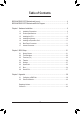
Table of Contents B550M AORUS ELITE Motherboard Layout....................................................................4 B550M AORUS ELITE Motherboard Block Diagram........................................................5 Chapter 1 Hardware Installation......................................................................................6 1-1 1-2 1-3 1-4 1-5 1-6 1-7 Installation Precautions..................................................................................... 6 Product Specifications.....
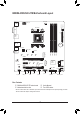
B550M AORUS ELITE Motherboard Layout LED_C2 Socket AM4 D_LED2 CPU_FAN ATX_12V KB_MS_USB ATX DVI HDMI U32_1 USB_LAN BAT SYS_FAN1 LED_CPU Realtek® GbE LAN PCIEX1 B550M AORUS ELITE 80 60 42 iTE Super I/O ® CODEC PCIEX4 CLR_CMOS F_AUDIO LED_C1 D_LED1 COM TPM F_U32 F_USB1 DDR4_B2 AMD B550 0 1 2 3 PCIEX16 SATA3 42 DDR4_B1 60 DDR4_A2 80 DDR4_A1 110 M_BIOS M2A_CPU AUDIO M2B_SB U32_2 QFLED SYS_FAN2 F_PANEL QFLASH_PLUS Box Contents 55 B550M AORUS ELITE motherboard 55 User'
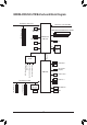
B550M AORUS ELITE Motherboard Block Diagram PCI Express 4.0/3.0 Bus CPU CLK+/- (100~500 MHz) x16 DDR4 3200/2933/2667/2400/2133 MHz 1 PCI Express x16 1 M.2 Socket 3 (M2A_CPU) 4 USB 3.2 Gen 1 AMD Socket AM4 CPU SPI Bus HDMI LPC Bus TPM iTE® Super I/O PCIe 3.0 x4 DVI-D BIOS CODEC Line In (Rear Speaker Out) Line Out (Front Speaker Out) MIC (Center/Subwoofer Speaker Out) 4 SATA 6Gb/s AMD B550 2 USB 3.2 Gen 1 6 USB 2.0/1.1 PCI Express 3.
Chapter 1 1-1 Hardware Installation Installation Precautions The motherboard contains numerous delicate electronic circuits and components which can become damaged as a result of electrostatic discharge (ESD). Prior to installation, carefully read the user's manual and follow these procedures: •• Prior to installation, make sure the chassis is suitable for the motherboard. •• Prior to installation, do not remove or break motherboard S/N (Serial Number) sticker or warranty sticker provided by your dealer.
1-2 Product Specifications CPU AMD Socket AM4, support for: 3rd Generation AMD Ryzen™ processors/ 3rd Generation AMD Ryzen™ with Radeon™ Graphics processors (Go to GIGABYTE's website for the latest CPU support list.
Storage Interface 1 x M.2 connector (M2A_CPU), integrated in the CPU, supporting Socket 3, M key, type 2242/2260/2280/22110 SSDs: - 3rd Generation AMD Ryzen™ processors support SATA and PCIe 4.0 x4/x2 SSDs - 3rd Generation AMD Ryzen™ with Radeon™ Graphics processors support SATA and PCIe 3.0 x4/x2 SSDs 1 x M.2 connector (M2B_SB), integrated in the Chipset, supporting Socket 3, M key, type 2242/2260/2280 SSDs: - Supporting SATA and PCIe 3.
Hardware Monitor BIOS Voltage detection Temperature detection Fan speed detection Overheating warning Fan fail warning Fan speed control * Whether the fan speed control function is supported will depend on the cooler you install. Unique Features 1 x 256 Mbit flash Use of licensed AMI UEFI BIOS PnP 1.0a, DMI 2.7, WfM 2.0, SM BIOS 2.7, ACPI 5.
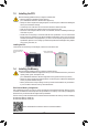
1-3 Installing the CPU Read the following guidelines before you begin to install the CPU: •• Make sure that the motherboard supports the CPU. (Go to GIGABYTE's website for the latest CPU support list.) •• Always turn off the computer and unplug the power cord from the power outlet before installing the CPU to prevent hardware damage. •• Locate the pin one of the CPU. The CPU cannot be inserted if oriented incorrectly. •• Apply an even and thin layer of thermal grease on the surface of the CPU.
Recommanded Dual Channel Memory Configuration: 2 Modules 4 Modules DDR4_A1 DDR4_A2 DDR4_B1 DDR4_B2 -- DS/SS -- DS/SS DS/SS DS/SS DS/SS DS/SS (SS=Single-Sided, DS=Double-Sided, "- -"=No Memory) Due to CPU limitations, read the following guidelines before installing the memory in Dual Channel mode. 1. Dual Channel mode cannot be enabled if only one memory module is installed. 2.
RJ-45 LAN Port The Gigabit Ethernet LAN port provides Internet connection at up to 1 Gbps data rate. The following describes the states of the LAN port LEDs. Connection/ Speed LED Activity LED Connection/Speed LED: LAN Port Activity LED: State Description State Orange 1 Gbps data rate Blinking Data transmission or receiving is occurring Description Green 100 Mbps data rate Off Off 10 Mbps data rate No data transmission or receiving is occurring USB 3.
1-7 Internal Connectors 3 1 7 5 2 16 4 6 9 9 8 10 7 5 15 14 13 12 17 11 4 18 1) ATX_12V 10) F_AUDIO 2) ATX 11) F_PANEL 3) CPU_FAN 12) F_U32 4) SYS_FAN1/SYS_FAN2 13) F_USB1 5) D_LED1/D_LED2 14) COM 6) LED_CPU 15) TPM 7) LED_C1/LED_C2 16) BAT 8) SATA3 0/1/2/3 17) CLR_CMOS 9) M2A_CPU/M2B_SB 18) QFLASH_PLUS Read the following guidelines before connecting external devices: •• First make sure your devices are compliant with the connectors you wish to connect.
1/2) ATX_12V/ATX (2x4 12V Power Connector and 2x12 Main Power Connector) With the use of the power connector, the power supply can supply enough stable power to all the components on the motherboard. Before connecting the power connector, first make sure the power supply is turned off and all devices are properly installed. The power connector possesses a foolproof design. Connect the power supply cable to the power connector in the correct orientation.
_3 _ F _0 5) D_LED1/D_LED2 (Addressable LED Strip Headers) F The headers can be used to connect a standard 5050 addressable LED strip, with maximum power rating of 5A (5V) and maximum number of 1000 LEDs. 1 Pin No. 1 2 3 4 1 D_LED1 D_LED2 B_ B_ B S F_ Addressable LED Strip Definition V (5V) Data No Pin GND Connect your addressable LED strip to the header. The power pin (marked with a triangle on the plug) of the LED strip must be connected to Pin 1 of the addressable LED strip header.
DEBUG 7) PORT LED_C1/LED_C2 (RGB LED Strip Headers) The headers can be used to connect a standard 5050 RGB LED strip (12V/G/R/B), with maximum power rating of 2A (12V) and maximum length of 2m. Pin No. 1 2 3 4 1 1 LED_C2 DEBUG PORT LED_C1 Definition 12V G R B Connect your RGB LED strip to the header. The power pin (marked with a triangle on the plug) of the LED strip must be connected to Pin 1 (12V) of this header. Incorrect connection may lead to the damage of the LED strip.
_ _ F _0 F 9) M2A_CPU/M2B_SB (M.2 Socket 3 Connectors) The M.2 connectors support M.2 SATA SSDs or M.2 PCIe SSDs and support RAID configuration. Please note that an M.2 PCIe B S_SSD cannot be used to create a RAID set either with an M.2 SATA SSD or a SATA B hard drive. Refer to Chapter 3, "Configuring a RAID Set," for instructions on configuring a RAID array. _ B M2A_CPU S B_ B 110 80 60 42 S S M2B_SB 80 _ S 60 42 _3 S_ _ B U Follow the steps below to correctly install an M.
11) F_PANEL (Front Panel Header) Connect the power switch, reset switch, speaker, chassis intrusion switch/sensor and system status indicator on the chassis to this header according to the pin assignments below. Note the positive and negative pins before connecting the cables. SPEAK+ NC NC SPEAK- PLED+ PLEDPW+ PW- Power LED Chassis Intrusion Header •• HD (Hard Drive Activity LED): Connects to the hard drive activity LED on the chassis front panel.
S U 1 2 S F_ 3 13) F_USB1 (USB 2.0/1.1 Header) The header conforms to USB 2.0/1.1 specification. Each USB header can provide two USB ports via an optional USB bracket. For purchasing the optional USB bracket, please contact the local dealer. Pin No. 1 2 3 4 5 1 2 9 10 _ B Definition Power (5V) Power (5V) USB DXUSB DYUSB DX+ Pin No. 6 7 8 9 B S_ 10 B Definition USB DY+ GND GND No Pin NC •• Do not plug the IEEE 1394 bracket (2x5-pin) cable into the USB 2.0/1.1 header.
16) BAT (Battery) The battery provides power to keep the values (such as BIOS configurations, date, and time information) in the CMOS when the computer is turned off. Replace the battery when the battery voltage drops to a low level, or the CMOS values may not be accurate or may be lost. You may clear the CMOS values by removing the battery: 1. Turn off your computer and unplug the power cord. 2. Gently remove the battery from the battery holder and wait for one minute.
Chapter 2 BIOS Setup BIOS (Basic Input and Output System) records hardware parameters of the system in the CMOS on the motherboard. Its major functions include conducting the Power-On Self-Test (POST) during system startup, saving system parameters and loading operating system, etc. BIOS includes a BIOS Setup program that allows the user to modify basic system configuration settings or to activate certain system features.
2-2 The Main Menu System Time Setup Menus Configuration Items Hardware Information Option Description Current Settings Quick Access Bar allows you to quickly move to the General Help, Easy Mode, Smart Fan 5, or Q-Flash screen.
2-3 Favorites (F11) Set your frequently used options as your favorites and use the key to quickly switch to the page where all of your favorite options are located. To add or remove a favorite option, go to its original page and press on the option. The option is marked with a star sign if set as a "favorite.
2-4 Tweaker Whether the system will work stably with the overclock/overvoltage settings you made is dependent on your overall system configurations. Incorrectly doing overclock/overvoltage may result in damage to CPU, chipset, or memory and reduce the useful life of these components. This page is for advanced users only and we recommend you not to alter the default settings to prevent system instability or other unexpected results.
Advanced CPU Settings && Core Performance Boost (Note 1) Allows you to determine whether to enable the Core Performance Boost (CPB) technology, a CPU performance-boost technology. (Default: Auto) && SVM Mode Virtualization enhanced by Virtualization Technology will allow a platform to run multiple operating systems and applications in independent partitions. With virtualization, one computer system can function as multiple virtual systems.
&& System Memory Multiplier Allows you to set the system memory multiplier. Auto sets memory multiplier according to memory SPD data. (Default: Auto) Advanced Memory Settings Memory Subtimings dd Standard Timing Control, Advanced Timing Control, CAD Bus Setup Timing, CAD Bus Drive Strength, Data Bus Configuration These sections provide memory timing settings. Note: Your system may become unstable or fail to boot after you make changes on the memory timings.
2-5 Settings Platform Power && AC BACK Determines the state of the system after the return of power from an AC power loss. Memory The system returns to its last known awake state upon the return of the AC power. Always On The system is turned on upon the return of the AC power. Always Off The system stays off upon the return of the AC power. (Default) && Power On By Keyboard Allows the system to be turned on by a PS/2 keyboard wake-up event.
&& Soft-Off by PWR-BTTN Configures the way to turn off the computer in MS-DOS mode using the power button. Instant-Off Press the power button and then the system will be turned off instantly. (Default) Delay 4 Sec. Press and hold the power button for 4 seconds to turn off the system. If the power button is pressed for less than 4 seconds, the system will enter suspend mode. && Power Loading Enables or disables dummy load.
&& UMA Frame Buffer Size (Note) Frame buffer size is the total amount of system memory allocated solely for the onboard graphics controller. MS-DOS, for example, will use only this memory for display. Options are: Auto (default), 64M~2G. This item is configurable only when UMA Mode is set to UMA Specified. && Display Resolution (Note) Allows you to set the display resolution. Options are: Auto (default), 1920x1080 and below, 2560x1600, 3840x2160.
NVMe Configuration Displays information on your M.2 NVME PCIe SSD if installed. SATA Configuration && SATA Mode Enables or disables RAID for the SATA controllers integrated in the Chipset or configures the SATA controllers to AHCI mode. RAID Enables RAID for the SATA controller. AHCI Configures the SATA controllers to AHCI mode.
Miscellaneous && LEDs in System Power On State Allows you to enable or disable motherboard LED lighting when the system is on. Off Disables the selected lighting mode when the system is on. On Enables the selected lighting mode when the system is on. (Default) && LEDs in Sleep, Hibernation, and Soft Off States Allows you to set the lighting mode of the motherboard LEDs in system S3/S4/S5 state. This item is configurable when LEDs in System Power On State is set to On.
Smart Fan 5 && Monitor Allows you to select a target to monitor and to make further adjustment. (Default: CPU FAN) && Fan Speed Control Allows you to determine whether to enable the fan speed control function and adjust the fan speed. Normal Allows the fan to run at different speeds according to the temperature. You can adjust the fan speed with System Information Viewer based on your system requirements. (Default) Silent Allows the fan to run at slow speeds.
2-6 System Info. This section provides information on your motherboard model and BIOS version. You can also select the default language used by the BIOS and manually set the system time. && System Language Selects the default language used by the BIOS. && System Date Sets the system date. The date format is week (read-only), month, date, and year. Use to switch between the Month, Date, and Year fields and use the or key to set the desired value.
2-7 Boot && Boot Option Priorities Specifies the overall boot order from the available devices. Removable storage devices that support GPT format will be prefixed with "UEFI:" string on the boot device list. To boot from an operating system that supports GPT partitioning, select the device prefixed with "UEFI:" string.
&& VGA Support Allows you to select which type of operating system to boot. Auto Enables legacy option ROM only. EFI Driver Enables EFI option ROM. (Default) This item is configurable only when Fast Boot is set to Enabled or Ultra Fast. && USB Support Disabled All USB devices are disabled before the OS boot process completes. Full Initial All USB devices are functional in the operating system and during the POST.
&& Administrator Password Allows you to configure an administrator password. Press on this item, type the password, and then press . You will be requested to confirm the password. Type the password again and press . You must enter the administrator password (or user password) at system startup and when entering BIOS Setup. Differing from the user password, the administrator password allows you to make changes to all BIOS settings.
2-8 Save & Exit && Save & Exit Setup Press on this item and select Yes. This saves the changes to the CMOS and exits the BIOS Setup program. Select No or press to return to the BIOS Setup Main Menu. && Exit Without Saving Press on this item and select Yes. This exits the BIOS Setup without saving the changes made in BIOS Setup to the CMOS. Select No or press to return to the BIOS Setup Main Menu.
Chapter 3 3-1 Appendix Configuring a RAID Set RAID Levels Minimum Number of Hard Drives Array Capacity Fault Tolerance RAID 0 ≥2 Number of hard drives * Size of the smallest drive No RAID 1 2 RAID 10 4 Size of the smallest drive (Number of hard drives/2) * Size of the smallest drive Yes Yes Before you begin, please prepare the following items: •• At least two SATA hard drives or SSDs.
C. UEFI RAID Configuration Steps: 1. In BIOS Setup, go to Boot and set CSM Support to Disabled. Save the changes and exit BIOS Setup. 2. After the system reboot, enter BIOS Setup again. Then enter the Settings\IO Ports\RAIDXpert2 Configuration Utility sub-menu. 3. On the RAIDXpert2 Configuration Utility screen, press on Array Management to enter the Create Array screen. Then, select a RAID level.
3-2 Drivers Installation •• Before installing the drivers, first install the operating system. •• After installing the operating system, insert the motherboard driver disc into your optical drive. Click on the message "Tap to choose what happens with this disc" on the top-right corner of the screen and select "Run Run.exe." (Or go to My Computer, double-click the optical drive and execute the Run.exe program.
Regulatory Notices United States of America, Federal Communications Commission Statement Supplier's Declaration of Conformity 47 CFR § 2.1077 Compliance Information Product Name: Motherboard Trade Name: GIGABYTE Model Number: B550M AORUS ELITE Responsible Party – U.S. Contact Information: G.B.T. Inc. Address: 17358 Railroad street, City Of Industry, CA91748 Tel.: 1-626-854-9338 Internet contact information: https://www.gigabyte.
- 42 -
- 43 -
Contact Us GIGA-BYTE TECHNOLOGY CO., LTD. Address: No.6, Baoqiang Rd., Xindian Dist., New Taipei City 231, Taiwan TEL: +886-2-8912-4000, FAX: +886-2-8912-4005 Tech. and Non-Tech. Support (Sales/Marketing) : https://esupport.gigabyte.com WEB address (English): https://www.gigabyte.com WEB address (Chinese): https://www.gigabyte.com/tw •• GIGABYTE eSupport To submit a technical or non-technical (Sales/Marketing) question, please link to: https://esupport.gigabyte.