GA-6LISL LGA1150 socket motherboard for Intel® E3 series processors User's Manual Rev.
Copyright © 2014 GIGA-BYTE TECHNOLOGY CO., LTD. All rights reserved. The trademarks mentioned in this manual are legally registered to their respective owners. Disclaimer Information in this manual is protected by copyright laws and is the property of GIGABYTE. Changes to the specifications and features in this manual may be made by GIGABYTE without prior notice.
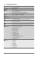
Table of Contents Box Contents....................................................................................................................5 GA-6LISL Motherboard Layout.........................................................................................6 GA-6LISL Block Diagram.................................................................................................8 Chapter 1 Hardware Installation......................................................................................
2-3-2 2-3-2-1 2-3-2-2 2-3-3 2-4 PCH-IO Configuration..............................................................................................69 PCI Express Configuration......................................................................................71 USB Configuration...................................................................................................72 Intel Server Platform Services.................................................................................
Box Contents GA-6LISL motherboard Driver CD Two SATA cables I/O Shield • The box contents above are for reference only and the actual items shall depend on the product package you obtain. The box contents are subject to change without notice. • The motherboard image is for reference only.
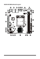
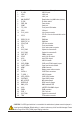
GA-6LISL Motherboard Layout 1 2 3 4 5 6 7 9 10 8 38 14 37 12 13 34 36 30 29 28 11 15 35 33 32 16 31 25 24 23 27 26 22 17 21 -6- 20 19 18
Item 1 2 3 4 5 6 7 8 9 10 Code R_USB1 LAN2 LAN1 NMI_BMCRST ID_SW PWR_SW COM1 FP_VGA1 VGA1 P12V_AUX1 11 CFG5 12 13 14 15 16 17 18 19 20 21 22 23 24 25 26 27 28 29 30 31 32 33 34 35 36 37 38 DDR3_P0_B0 DDR3_P0_A0 CPU0_FAN FP_1 ATX1 SYS_FAN2 SYS_FAN3 PWR_DET CPU0 U516 F_USB3 SATA_DOM4 CASE_OPEN HDMI BAT SATA0~4 F_USB2_1 SATA_SGPIO CLRCMOS ME_UPDATE BIOSRCVR BMC_LED1 U546 IPMB1 PCIE_1 SYS_FAN1 TPM Description USB 2.
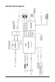
GA-6LISL Block Diagram -8-
Chapter 1 1-1 Hardware Installation Installation Precautions The motherboard contains numerous delicate electronic circuits and components which can become damaged as a result of electrostatic discharge (ESD). Prior to installation, carefully read the user's manual and follow these procedures: • Prior to installation, do not remove or break motherboard S/N (Serial Number) sticker or warranty sticker provided by your dealer. These stickers are required for warranty validation.
1-2 Product Specifications CPU Support for Intel® Xeon® E3-1200 V3 family processors in the LGA1150 package L3 cache varies with CPU Chipset Intel® C226 chipset Memory LAN Onboard Graphics Storage Interface USB Expansion Slots Internal Connectors Back Panel Connectors Hardware Installation 2 x 1.35V/1.
I/O Controller ASPEED ® AST2300 BMC chip Hardware Monitor System voltage detection CPU/System temperature detection CPU/System fan speed detection CPU/System fan speed control * Whether the CPU/system fan speed control function is supported will depend on the CPU/system cooler you install. BIOS 1 x 128 Mbit flash AMI BIOS Form Factor Mini ITX Form Factor; 6.7 inch x 6.
1-3 Installing the CPU and CPU Cooler Read the following guidelines before you begin to install the CPU: • Make sure that the motherboard supports the CPU. • Always turn off the computer and unplug the power cord from the power outlet before installing the CPU to prevent hardware damage. • Locate the pin one of the CPU. The CPU cannot be inserted if oriented incorrectly. (Or you may 6LISL-S_V1.1 locate the notches on both sides of the CPU and alignment keys on the CPU socket.
B. Follow the steps below to correctly install the CPU into the motherboard CPU socket. Before installing the CPU, make sure to turn off the computer and unplug the power cord from the power outlet power plug to prevent any damage to prevent damage to the CPU. Step 1: Gently press the CPU socket lever handle down and away from the socket with your finger. Then completely lift the CPU socket lever and the metal load plate will be lifted as well. Step 2: Remove the CPU socket cover as shown.
1-3-2 Installing the CPU Cooler Follow the steps below to correctly install the CPU cooler on the motherboard. (The following procedure uses Intel® boxed cooler as the example cooler.) Male Push Pin Direction of the Arrow Sign on the Male Push Pin The Top of Female Push Pin Female Push Pin Step 1: Apply an even and thin layer of thermal paste on the surface of the installed CPU. Step 3: Place the cooler atop the CPU, aligning the four push pins through the pin holes on the motherboard.
1-4 Installing the Memory Read the following guidelines before you begin to install the memory: • Make sure that the motherboard supports the memory. It is recommended that memory of the same capacity, brand, speed, and chips be used. • Always turn off the computer and unplug the power cord from the power outlet before installing the memory to prevent hardware damage. • Memory modules have a foolproof design. A memory module can be installed in only one direction.
1-4-2 Installing a Memory Before installing a memory module, make sure to turn off the computer and unplug the power cord from the power outlet to prevent damage to the memory module. Be sure to install DDR3 DIMMs on this motherboard. Installation Step: Step 1. Insert the DIMM memory module vertically into the DIMM slot, and push it down. Step 2. Close the plastic clip at both edges of the DIMM slots to lock the DIMM module. NOTE! For dual-channel operation, DIMMs must be installed in matched pairs. Step 3.
1-5 Back Panel Connectors VGA Port The video in port allows connect to video in, which can also apply to video loop thru function. Serial Port Connects to serial-based mouse or data processing devices. Power Button and LED Press this button to hard reset and power on the system. Color Status Green On Green Blink N/A Off Description System is powered on.
I210 Speed LED: Speed LED Link Activity LED 10/100/1000 LAN Port State Yellow On Yellow Blink Green On Green Blink Off Link/Activity LED: Description 1 Gbps data rate Identif y 1 Gbps data rate 100 Mbps data rate Identify 100 Mbps data rate 10 Mbps data rate State On Description Link bet ween system and net work or no access Blinking Data transmission or receiving is occurring Off No data transmission or receiving is occurring • When removing the cable connected to a back panel connector, first remov
1-6 Internal Connectors 2 16 17 27 3 4 13 19 20 24 23 18 15 9 11 1 25 21 26 27 5 8 10 12 7 22 14 1) 2) 3) 4) 5) 6) 7) 8) 9) 10) 11) 12) 13) 14) ATX1 P12V_AUX1 CPU0_FAN (CPU Fan) SYS_FAN1 (System Fan) SYS_FAN2 (System Fan) SYS_FAN3 (System Fan) PWR_DET SATA0 SATA1 SATA2 SATA3 SATA4 FP_1 F_USB3 15) 16) 17) 18) 19) 20) 21) 22) 23) 24) 25) 26) 27) 28) 6 F_USB2_1 FP_VGA1 TPM SGPIO_SATA IPMB1 BMC_LED1 HDMI BAT CLRCMOS BIOSRCVR ME_UPDATE CASE_OPEN SATA_DOM4 CFG5 Read the following guidelines bef
Stick 1/2) ATX1/P12V_AUX1 (2x12 Main Power Connector and 2x2 12V Power Connector) With the use of the power connector, the power supply can supply enough stable power to all the components on the motherboard. Before connecting the power connector, first make sure the power supply is turned off and all devices are properly installed. The power connector possesses a foolproof design. Connect the power supply cable to the power connector in the correct orientation.
3/4/5/6) CPU0_FAN/SYS_FAN1/SYS_FAN2/SYS_FAN3 (CPU Fan/System Fan Headers) The motherboard has a 4-pin CPU fan header (CPU0_FAN), and three 4-pin (SYS_FAN1/SYS_ FAN2/SYS_FAN3) system fan headers. Most fan headers possess a foolproof insertion design. When connecting a fan cable, be sure to connect it in the correct orientation (the black connector wire is the ground wire). The motherboard supports CPU fan speed control, which requires the use of a CPU fan with fan speed control design.
8/9/10/11/12) SATA0/SATA1/SATA2/SATA3/SATA4 (SATA 6Gb/s Connectors) The SATA connectors conform to SATA 6Gb/s standard and are compatible with SATA 3Gb/s and 1.5Gb/s standard. Each SATA connector supports a single SATA device. 7 7 1 1 When SATA_DOM4 jumper are When SATA_DOM4 jumper are set to 1-2 pin: set to 2-3 pin: SATA0 SATA1 SATA2 SATA3 SATA4 Pin No. 1 2 3 4 5 6 7 Definition GND TXP TXN GND RXN RXP P5V Pin No.
13) FP_1 (Front Panel Header) Connect the power switch, reset switch, chassis intrusion switch/sensor and system status indicator on the chassis to this header according to the pin assignments below. Note the positive and negative pins before connecting the cables. 1 2 23 24 Pin No.
14) F_USB3 (USB 3.0 Header) The headers conform to USB 3.0 specification. Each USB header can provide two USB ports via an optional USB bracket. For purchasing the optional USB bracket, please contact the local dealer. 20 11 1 10 Pin No. 1 2 3 4 5 6 7 8 9 10 11 12 13 14 15 16 17 18 19 20 Definition Power IntA_P1_SSRXIntA_P1_SSRX+ GND IntA_P1_SSTXIntA_P1_SSTX+ GND IntA_P1_DIntA_P1_D+ NC IntA_P2_D+ IntA_P2_DGND IntA_P2_SSTX+ IntA_P2_SSTXGND IntA_P2_SSRX+ IntA_P2_SSRXPower No Pin 15) F_USB2_1 (USB 2.
16) FP_VGA1 (Front panel VGA header) 2 1 12 11 Pin No. 1 2 3 4 5 6 7 8 9 10 11 12 Definition V-Sync H-Sync Power (5V) Clock Enable (active low) Data Blue GND Green GND Red No Pin 17) TPM (TPM Module connector) 13 14 Pin No.
18) SATA_SGPIO (SATA SGPIO Header) SGPIO is stands for Serial General Purpose Input/Output which is a 4-signal (or 4-wire) bus used between a Host Bus Adapter (HBA) and a backplane. Out of the 4 signals, 3 are driven by the HBA and 1 is driven by the backplane. Typically, the HBA is a storage controller located inside a server, desktop, rack or workstation computer that interfaces with Hard disk drives (HDDs) to store and retrieve data. Pin No.
20) BMC_LED1 (BMC Firmware Readiness LED) State On Blinking Off Description BMC firmware is initial BMC firmware is ready System is powered off 21) HDMI (HDMI Connector) The HDMI port is HDCP compliant and supports Dolby True HD and DTS HD Master Audio formats. It also supports up to 192KHz/24bit 8-channel LPCM audio output. You can use this port to connect your HDMI-supported monitor.
22) BAT (Battery cable connector) The battery provides power to keep the values (such as BIOS configurations, date, and time information) in the CMOS when the computer is turned off. Replace the battery when the battery voltage drops to a low level, or the CMOS values may not be accurate or may be lost. 2 Pin No. 1 2 1 Definition RTC Reset GND • Always turn off your computer and unplug the power cord before replacing the battery. • Replace the battery with an equivalent one.
24) BIOSRCVR (BIOS Recovery Jumper) 1 1-2 Close: Normal operation. (Default setting) 1 2-3 Close: BIOS recovery mode. 25) ME_UPDATE (ME Recover Jumpers) - 29 - 1 1-2 Close: ME recovery mode.
26) CASE_OPEN (Case open intrusion header) Open: Active chassis intrustion alert. Closed: Normal operation. 27) SATA_DOM4 (SATA port 4 DOM Jumpers) CAUTION! • If the SATA DOM power is supplied by the motherboard, set the jumper to pin 1-2. • If the SATA DOM power is supplied by external power, set the jumper to pin 2-3. • If a SATA type hard drive is connected to the motherboard, please ensure the jumper is closed and set to 2-3 pins (Default setting), in order to reduce any risk of hard disk damage.
28) CFG5 (PCIE_1 bandwidth switch Jumper) 1 1 - 31 - 1-2 Close: PCIE_1 operates in x16 bandwidth. (Default setting) 2-3 Close: PCIE_1 operates in x8 bandwidth.
Chapter 2 BIOS Setup BIOS (Basic Input and Output System) records hardware parameters of the system in the EFI on the motherboard. Its major functions include conducting the Power-On Self-Test (POST) during system startup, saving system parameters and loading operating system, etc. BIOS includes a BIOS Setup program that allows the user to modify basic system configuration settings or to activate certain system features.
Main This setup page includes all the items in standard compatible BIOS. Advanced This setup page includes all the items of AMI BIOS special enhanced features. (ex: Auto detect fan and temperature status, automatically configure hard disk parameters.) Chipset This setup page includes all the submenu options for configuring the function of North Bridge and South Bridge. (ex: Auto detect fan and temperature status, automatically configure hard disk parameters.
2-1 The Main Menu Once you enter the BIOS Setup program, the Main Menu (as shown below) appears on the screen. Use arrow keys to move among the items and press to accept or enter other sub-menu. Main Menu Help The on-screen description of a highlighted setup option is displayed on the bottom line of the Main Menu. Submenu Help While in a submenu, press to display a help screen (General Help) of function keys available for the menu. Press to exit the help screen.
BIOS Information BIOS Version Display version number of the BIOS setup utility. BIOS Build Date and Time Displays the date and time when the BIOS setup utility was created. BMC Information BMC Firmware Version Display version number of the BMC setup utility. SDR Version Display the SDR version of the BMC setup utility. FRU Version Display the FRU version of the BMC setup utility.
2-2 Advanced Menu The Advanced menu display submenu options for configuring the function of various hardware components. Select a submenu item, then press Enter to access the related submenu screen.
2-2-1 ACPI Configuration ACPI Settings ACPI Sleep State Select the highest ACPI sleep state the system will enter, when the suspend button is pressed. Options available: Suspend Disabled/S1 only (CPU Stop Clock) for OS to choose from. Default setting is S1 only (CPU Stop Clock).
2-2-2 Trusted Computing (Optional) Configuration Security Device Support Select Enabled to activate TPM support feature. Options available: Enabled/Disabled. Default setting is Disabled. Current Status Information Display current TPM status information.
2-2-3 PCI Subsystem Settings PCI Express Slot #1 I/O ROM When enabled, This setting will initialize the device expansion ROM for the related PCI-E slot. Options available: Enabled/Disabled. Default setting is Enabled. Onboard LAN I/O ROM Option Configure onboard LAN devices and initialize device expansion ROM. Options available: PXE/iSCSI. Default setting is PXE. Onboard LAN1/2 I/O ROM Enable/Disable onboard LAN devices and initialize device expansion ROM. Options available: Enabled/Disabled.
VGA Palette Snoop Enable/Disable VGA Palette Tegisters Snooping. Options available: Enabled/Disabled. Default setting is Disabled. PERR Generation When this item is set to enabled, PCI bus parity error (PERR) is generated and is routed to NMI. Options available: Enabled/Disabled. Default setting is Disabled. SERR Generation When this item is set to enabled, PCI bus system error (SERR) is generated and is routed to NMI. Options available: Enabled/Disabled. Default setting is Disabled.
2-2-3-1 PCI Express Settings PCI Express Device Register Settings Relaxed Ordering Enable/DIsable PCI Express Device Relaxed Ordering feature. Options available: Enabled/Disabled. Default setting is Disabled. Extended Tag Wnen this feature is enabled, the system will allow device to use 8-bit Tag field as a requester. Options available: Enabled/Disabled. Default setting is Disabled. No Snoop Enable/Disable PCI Express Device No Snoop option. Options available: Enabled/Disabled.
Link Training Retry Define the number of Retry Attempts software wil take to retrain the link if previous training attempt was unsuccessful. Press <+> / <-> keys to increase or decrease the desired values. Link Training Timeout (us) Define the number of Microseconds software will wait before polling 'Link Training' bit in Link Status register. Press <+> / <-> keys to increase or decrease the desired values. Value rang is from 10 to 10000 us.
2-2-4 CPU Configuration - 43 - BIOS Setup
CPU Configuration CPU Type/Signature/Processor Family/Microcode Patch/FSB Speed/Max CPU Speed/ Min CPU Speed/Processor Cores/Intel HT Technology/Intel VT-x Technology/ Intel SMX Technology Displays the technical specifications for the installed processor. 64-bit Display the supported information of installed CPU. EIST Technology Display Intel EIST Technology function support information. CPU C3 state Display the support information of CPU C3 state feature.
Active Processor Cores (Note) Allows you to determine whether to enable all CPU cores. Options available: All/1/2/3. Default setting is All. Overclocking lock Enable/Disable Overclocking lock. Options available: Enabled/Disabled. Default setting is Disabled. Limit CPUID Maximum When enabled, the processor will limit the maximum COUID input values to 03h when queried, even if the processor suppports a higher CPUID input value.
Turbo Mode When this item is enabled, tje processor will automatically ramp up the clock speed of 1-2 of its processing cores to improve its performance. When this item is disabled, the processor will not overclock any of its core. Options available: Enabled/Disabled. Default setting is Enabled. Energy Performance Energy Performance Bias is Intel CPU function. The larger value in MSR_ENERGY_PERFORMANCE_BIAS register, CPU will save more power but lose more performance.
Package C State Limit Configure state for the C-State package limit. Options available: C0/C1/C3/C6/C7/C7s/C8/C9/C10/Auto. Default setting is Auto. Intel TXT (LT) Support Enable/Disable Intel TXT (LT) support. Options available: Enabled/Disabled. Default setting is Disabled. ACPI T State Enable/Disable ACPI T state support. Options available: Enabled/Disabled. Default setting is Disabled. CPU DTS Enable/Disable CPU DTS support. Options available: Enabled/Disabled. Default setting is Disabled.
2-2-5 SATA Configuration BIOS Setup - 48 -
SATA Controller(s) Enable/Disable the SATA controller. Options available: Enabled/Disabled. Default setting is Enabled. SATA Mode Selection Select the on chip SATA type. IDE Mode: When set to IDE, the SATA controller disables its RAID and AHCI functions and runs in the IDE emulation mode. This is not allowed to access RAID setup utility. RAID Mode: When set to RAID, the SATA controllerenables both its RAID and AHCI functions. You will be allows access the RAID setup utility at boot time.
2-2-5-1 Software Feature Mask Configuration RAID 0 Enable/Disable RAID 0 feature. Options available: Enabled/Disabled. Default setting is Enabled. RAID 1 Enable/Disable RAID 1 feature. Options available: Enabled/Disabled. Default setting is Enabled. RAID 10 Enable/Disable RAID 10 feature. Options available: Enabled/Disabled. Default setting is Enabled. RAID 5 Enable/Disable RAID 5 feature. Options available: Enabled/Disabled. Default setting is Enabled.
LED Locate When this item is enabled, the LED/SGPIO hardware is attached and ping to locate feature is enabled on the OS. Options available: Enabled/Disabled. Default setting is Enabled. IRRT Only on eSATA When this item is enabled, only IRRT volumes can span internal and eSATA drives. If disabled, then any RAID volue can span internal and eSATA drives Options available: Enabled/Disabled. Default setting is Enabled. Smart Response Technlogy Enable/Disable Intel Smart Response Technlogy.
2-2-6 Info Report Configuration Info Report Configuration Post Report Enable/Disable Post Report support. Options available: Enabled/Disabled. Default setting is Enabled. Delay Time Options available: 0/1/2/3/4/5/6/78/9/10/Util Press ESC. Default setting isUntil Press ESC. Error Message Report Info Error Message Enable/Disable Info Error Message support. Options available: Enabled/Disabled. Default setting is Enabled. Summary Screen Summary Screen Enable/Disable Summary Screen support.
2-2-7 USB Configuration Legacy USB Support Enables or disables support for legacy USB devices. Options available: Auto/Enabled/Disabled. Default setting is Enabled. XHCI Hand-off Enable/Disable XHCI (USB 3.0) Hand-off support. Options available: Enabled/Disabled. Default setting is Enabled. EHCI Hand-off Enable/Disable EHCI (USB 2.0) Hand-off function. Options available: Enabled/Disabled. Default setting is Disabled.
2-2-8 Super IO Configuration BIOS Setup - 54 -
Super IO Chip Display the model name of Super IO chip. Serial Port 0 Configuration Serial Port 0 When enabled allows you to configure the serial port settings. When set to Disabled, displays no configuration for the serial port. Options available: Enabled/Disabled. Default setting is Enabled. Device Settings Display the Serial Port 0 base I/O addressand IRQ. Change Settings Change Serial Port 0 device settings. When set to Auto allows the server’s BIOS or OS to select a configuration.
2-2-9 Serial Port Console Redirection BIOS Setup - 56 -
COM1/Serial Port for Out-of Band Management/Windows Emergency Management Service (EMS) Console Redirection (Note) Select whether to enable console redirection for specified device. Console redirection enables users to manage the system from a remote location. Options available: Enabled/Disabled. Default setting is Disabled. Console Redirection Settings Terminal Type Select a terminal type to be used for console redirection. Options available: VT100/VT100+/ANSI /VT-UTF8.
Mark and Space Parity do not allow for error detection. Options available: None/Even/Odd/Mark/Space. Stop Bits Stop bits indicate the end of a serial data packet. (A start bit indicates the beginning). The standard setting is 1 stop bit. Communication with slow devices may require more than 1 stop bit. Options available: 1/2. Flow Control Flow control can prevent data loss from buffer overflow. When sending data, if the receiving buffers are full, a 'stop' signal can be sent to stop the data flow.
2-2-10 Network Stack Network stack Enable/Disable UEFI network stack. Options available: Enabled/DIsabled. Default setting is Disabled. Ipv4 PXE Support(Note) Enable/Disable Ipv4 PXE feature. Options available: Enabled/DIsabled. Default setting is Enabled. Ipv6 PXE Support(Note) Enable/Disable Ipv6 PXE feature. Options available: Enabled/DIsabled. Default setting is Enabled. (Note) This item appears when Network Stack is set to Enabled.
2-2-11 iSCSI Configuration iSCSI Initiator Name Add an Attempts Press [Enter] for configuration of advanced items. Delete Attempts Press [Enter] for configuration of advanced items. Change Attempt Order Press [Enter] for configuration of advanced items.
2-2-12 Intel (R) I210 Gigabit Network Connection - 61 - BIOS Setup
PORT CONFIGURATION MENU NIC Configuration Press [Enter] for configuration of advanced items. Blink LEDs (range 0-15 seconds) Blink LEDs for the specified duration (up to 15 seconds). Press the numberic keys to input the desired value. PORT CONFIGURATION INFORMATION UEFI Driver Display the UEFI driver information. Adapter PBA Display the Adapter PBA information. Chip Type Display the Chip type. PCI Device ID Display the PCI device ID.
2-3 Chipset Menu The Chipset menu display submenu options for configuring the function of North Bridge and South Bridge. Select a submenu item, then press Enter to access the related submenu screen.
2-3-1 System Agent (SA)Configuration System Agent Bridge Name Display the System Agent (SA) Bridge Name. System Agent RC Version Display the version number of System Agent RC. VT-d Capability Display the VT-d support information. VT-d Enable/Disable Intel Virtualization Technology for Directed I/O (VT-d) feature. Options available: Enabled/DIsabled. Default setting is Enabled. Options available: Enabled/DIsabled. Default setting is Enabled. Enable NB CRID Options available: Enabled/DIsabled.
2-3-1-1 Graphic Configuration Graphic Configuration Primary Display Device Configure the Primary display device. Options available: Auto/IGFX(if the CPU support graphic)/PEG/Onboard VGA. Default setting is Auto.
2-3-1-2 NB PCIe Configuration NB PCIe Configuration PEG0 Display PEG0 configuration information. PEG0 - Gen X Configure PEG0 B0:D1:F0 Gen1-Gen3. Options available: Auto/Gen1/Gen2/Gen3. Default setting is Auto. PEG1 Display PEG1 configuration information. PEG1 - Gen X Configure PEG1 B0:D1:F1 Gen1-Gen3. Options available: Auto/Gen1/Gen2/Gen3. Default setting is Auto. PEG2 Display PEG2 configuration information. PEG2 - Gen X Configure PEG2 B0:D1:F2 Gen1-Gen3. Options available: Auto/Gen1/Gen2/Gen3.
Detect Non-Compliance Device Detect Non-Compliance PCI Express Device in PEG. Options available: Enabled/Disabled. Default setting is Disabled. Program PCIe ASPM after OpROM Enable/Disable Program PCIe ASPM after OpROM. Options available: Enabled/Disabled. Default setting is Disabled. PEG0 De-emphasis Control PEG0:Configure the De-emphasis control on PEG. Options available: Options available: -6 dB/-3.5 dB. Default setting is -3.5 dB.
2-3-1-3 Memory Configuration Memory Information Memory RC Version Display version number of installed memeory. Memory Frequency Display the frequency information of installed memory. Total Memory Determines how much total memory is present during the POST. Memory Voltage Display the voltage information of installed memory. DIMM Information: DDR3_P0_A0/DDR3_P0_A1/DDR3_P0_B0/DDR3_P0_B1 Status The size of memory installed on each of the DDR3 slots.
Memory Frequency Limiter Maximum Memory Frequency Selections in Mhz. Options available: Auto/1067/1333/1600/1867/2133/2400/2667. Default setting is Auto. Max TOLUD Maximum Value of TOLUD. Dynamic assignment would adjust TOLUD automatically based on largest MMIO length of installed graphic controller. Options available: Dynamic/3.5 GB/3.25 GB/3 GB/2.75 GB/2.5 GB/2.25 GB/2 GB/1.75 GB/1.5 GB/ 1.25 GB/1 GB. Default setting is Dynamic.
2-3-2 PCH-IO Configuration Intel PCH RC Version/Intel PCH SKU/Intel PCH Rev ID Information Displays the RC version, SKU and Reverison ID information of PCH. PCI Express Configuration Press [Enter] for configuration of advanced items. USB Configuration Press [Enter] for configuration of advanced items. DeepSx Power Policies Configure the DeepSx Mode configuration. Options available: Disabled/Enabled in S5/Enabled in S4-S5. Default setting is Disabled.
SLP_S4 Assertion Width Select a minimum assertion width of the SLP_S4# signal. Options available: 1-2 Seconds/2-3 Seconds/3-4 Seconds/4-5 Seconds. Default setting is 4-5 Seconds. Restore AC Power Loss This option provides user to set the mode of operation if an AC / power loss occurs. Power On: System power state when AC cord is re-plugged. Power Off: Do not power on system when AC power is back. Last State: Set system to the last sate when AC power is removed.
2-3-2-1 PCI Express Configuration PCI Express Clock Gating Enable/Disable PCI Express Clock Gating for each root port. Options available: Enabled/Disabled. Default setting is Enabled. DMI Link ASPM Control The control of Active State Power Management on both NB side and SB side of the DMI Link. Options available: Enabled/Disabled. Default setting is Disabled. DMI Link Extended Synch Control The control of Extended Synch on SB side of the DMI Link. Options available: Enabled/Disabled.
2-3-2-2 USB Configuration USB Configuration USB Precondition Precondition work on USB host controller and root ports for faster enumeration. Options available: Enabled/Disabled. Default setting is Disabled. XHCI Mode Mode of operation of xHCI controller. Options available: Smart Auto/Auto/Enabled/Disabled/Manual. Default setting is Smart Auto. BTCG Options available: Enabled/Disabled. Default setting is Enabled. USB Ports Per-Port Disable Control Control each of the USB ports (0~13) disabling.
2-3-3 Intel Server Platform Services Intel Server Platform Services Enable/Disable Intel Server Platform Services Help. Options available: Enabled/Disabled. Default setting is Enabled.
2-4 Security Menu The Security menu allows you to safeguard and protect the system from unauthorized use by setting up access passwords. There are two types of passwords that you can set: • Administrator Password Entering this password will allow the user to access and change all settings in the Setup Utility. • User Password Entering this password will restrict a user’s access to the Setup menus. To enable or disable this field, a Administrator Password must first be set.
2-4-1 Secure Boot menu The Secure Boot Menu is applicable when your device is installed the Windows® 8 operatin system. Platform Mode Display the System Platform Mode State. Secure Boot Display the status of Secure Boot. Secure Boot Control Enable/Disable Secure Boot function. Options available: Enabled/Disabled. Default setting is Disabled. Secure Boot Mode Secure Boot requires all the applications that are running during the booting process to be pre-signed with valid digital certificates.
2-4-1-1 Image Execution Policy Image Execution policy Internal FV Image Execution Policy per device path on Security Violation. Options available: Always Execute. Default setting is Always Execute. Option ROM Image Execution Policy per device path on Security Violation. Options available: Always Execute/Always Deny/Allow Execute/Defer Execute/ Deny Execute/ Query User. Default setting is Deny Execute. Removable Media Image Execution Policy per device path on Security Violation.
2-4-1-2 Key Management Key Management This item appears only when the Secure Boot Mode is set to Custom. Factory Default Key Provisioning Force the system to Setup Mode. This will clear all Secure Boot Variables such as Platform Key (PK), Key-exchange Key (KEK), Authorized Signature Database (db), and Forbidden Signaures Database (dbx). Options available: Enabled/Disabled. Default setting is Disabled. Install All Factory Default Keys Press [Enter] to install all factory default keys.
Set new KEK Press [Enter] to configure a new KEK. Append Var to KEK Press [Enter] to load additional KEK from a storage devices for an additional db and dbx management. Authorized Signature Database (DB) Display the status of Authorized Signature Database. Delete DB Press [Enter] to delete the db from your system. Set new DB Press [Enter] to configure a new db. Append aVar to DB Press [Enter] to load additional db from a storage devices.
2-5 Server Management Menu BMC LAN Configuration BMC LAN Configuration. Press Enter to access the related submenu. View FRU information The FRU information submenu is a simple display page for basic system ID information, as well as system product information. Items on this window are non-configurable. System Event Log Displays Event Log advanced settings. Press Enter to access the related submenu.
2-5-1 BMC LAN Configuration Lan Channel 1 Configuration Source Select to configure LAN channel parameters statically or dynamically (DHCP). Do nothing option will not modify any BMC network parameters during BIOS phase. Options available: Static/Dynamic/Do Nothing. IP Address(Note) Display IP Address information. Subnet Mask(Note) Display Subnet Mask information. Please note that the IP address must be in three digitals, for example, 192.168.000.001.
2-5-2 View FRU Information The FRU Information menu is a simple display page for basic system ID information, as well as System product information. Items on this window are non-configurable.
2-5-3 System Event Log Enabling/Disabling Options SEL Components Change this to enable or disable all features of System Event Logging during boot. Options available: Enabled/Disabled. Default setting is Disabled. Erasing Settings Erasing SEL Choose options for erasing Smbios Event Log Erasing is done prior to any logging activation during reset. Options available: No/Yes, On next reset/Yes, On every reset. Default setting is No. When SEL is Full Choose options for reactions to a full System Event Log.
2-6 Event Logs Menu Change Smbios Event Log Settings Press [Enter] for configuration of advanced items. View Smbios Event Log Press [Enter] to view event logs.
2-6-1 Change Smbios Event Log Settings Enabling/Disabling Options Smbios Event Log Choose options to Enable/Disable logging of System boot event. Options available: Enabled/Disabled. Default setting is Enabled. Erasing Settings Erasing Event Log Choose options for erasing Smbios Event Log Erasing is done prior to any logging activation during reset. Options available: No/Yes, On next reset/Yes, On every reset. Default setting is No.
METW Multiple Event Time Window: The number of minutes which must pass between duplicate log entries which utilize a multiple-event counter. The value ranges from 0 to 99 minutes. Press <+> / <-> keys to increase or decrease the desired values. Custom Options Log OEM Codes Enable/Disable the logging of EFI Status Codes as OEM Codes. Options available: Enabled/Disabled. Default setting is Disabled. Convert OEM Codes Enable/Disable the converting of EFI Status Codes to Standard Smbios Type.
2-6-2 View Smbios Event Log The Smbios Event Log is a display page of Smbios Event Log information. Items on this window are nonconfigurable.
2-7 Boot Menu The Boot menu allows you to set the drive priority during system boot-up. BIOS setup will display an error message if the legacy drive(s) specified is not bootable. Boot Configuration Setup Prompt Timeout Number of seconds to wait for setup activation key. 65535(0xFFFF) means indefinite waiting." Press the numberic keys to input the desired value. Bootup NumLock State Enable or Disable Bootup NumLock function. Options available: On/Off. Default setting is On.
Hard Drive BBS Priorities Press Enter to configure the boot priority. Network Device BBS Priorities Press Enter to configure the boot priority. CSM16 Parameters Press [Enter] for configuration of advanced items. CSM parameters Press [Enter] for configuration of advanced items.
2-7-1 CSM16 Parameters CSM16 Module Version Display CSM Module version information. Gate20 Active Upon Request: GA20 can be disabled using BIOS services. Always: Do not allow disabling GA20; this option is useful when any RT code is executed above 1MB. Options available: Upon Request/Always. Default setting is Upon Request. Option ROM Messages Option ROM Messages. Options available: Force BIOS/Keep Current. Default setting is Force BIOS.
2-7-2 CSM Parameters CSM parameters Press Enter to configure the advanced items. Launch CSM (Compatibility Support Module) Enable/Disable Compatibility Support Module (CSM) launch. Options available: Enabled/Disabled. Default setting is Enabled. • The following five items appears and configurable when the Launch CSM is set to Enabled. • If the Launch CSM is set to Disabled, the following five items will not be able to support Legacy mode. Boot option filter Determines which devices system will boot to.
Other PCI device ROM priority For PCI devices other than Network, Mass storage or Video device, defines which OpROM to launch. Options available: UEFI OpROM/Legacy OpROM. Default setting is UEFI OpROM.
2-8 Exit Menu The Exit menu displays the various options to quit from the BIOS setup. Highlight any of the exit options then press Enter. Save Changes and Exit Saves changes made and close the BIOS setup. Options available: Yes/No. Discard Changes and Exit Discards changes made and close the BIOS setup. Options available: Yes/No. Save Options Save Changes Saves changes made in the BIOS setup. Options available: Yes/No. Restore Defaults Loads the default settings for all BIOS setup parameters.
2-9 BIOS Beep Codes # of Beeps 1 2 4 4 5 6 BIOS Setup Description Invalid password Recovery started S3 Resume failed DXEIPL was not found No Console Input/Output Devices are found Flash update is failed - 94 -
2-10 BIOS Recovery Instruction The system has an embedded recovery technique. In the event that the BIOS becomes corrupt the boot block can be used to restore the BIOS to a working state. To restore your BIOS, please follow the instructions listed below: Recovery Instruction: 1. 2. 3. Change xxx.ROM to amiboot.rom. Copy amiboot.rom and AFUDOS.exe to USB diskette. Setting BIOS Recovery jump to enabled status. BIOS Recovery Jumper 4. 5. 6. Boot into BIOS recovery. Run Proceed with flash update.
Chapter 3 3-1 Appendix Regulatory Statements Regulatory Notices This document must not be copied without our written permission, and the contents there of must not be imparted to a third party nor be used for any unauthorized purpose. Contravention will be prosecuted. We believe that the information contained herein was accurate in all respects at the time of printing. GIGABYTE cannot, however, assume any responsibility for errors or omissions in this text.
Finally, we suggest that you practice other environmentally friendly actions by understanding and using the energy-saving features of this product (where applicable), recycling the inner and outer packaging (including shipping containers) this product was delivered in, and by disposing of or recycling used batteries properly.