
User`s manual


- 7 -
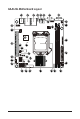
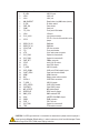
Item Code Description
1 R_USB1 USB 2.0 ports
2 LAN2 LAN2 port
3 LAN1 LAN1 port
4 NMI_BMCRST Reset button (top)/NMI button (bottom)
5 ID_SW ID Switch button
6 PWR_SW Power button
7 COM1 Serial port
8 FP_VGA1 Front panel VGA header
9 VGA1 VGA port
10 P12V_AUX1 4 pin power connector
11 CFG5
PCI-E x16 and x8 bandwidth switch
jumper
12 DDR3_P0_B0 DIMM slot
13 DDR3_P0_A0 DIMM slot
14 CPU0_FAN CPU fan connector
15 FP_1 Front panel header
16 ATX1 24 pin main power connector
17 SYS_FAN2 System fan connector#2
18 SYS_FAN3 System fan connector#3
19 PWR_DET PMBus connector
20 CPU0 Intel LGA1150 socket
21 U516 Intel C226 chipset
22 F_USB3 USB 3.0 header
23 SATA_DOM4 SATA port 4 DOM support jumper
24 CASE_OPEN Case open intrusion header
25 HDMI HDMI connector
26 BAT Battery power cable connector
27 SATA0~4 SATA 6Gb/s connectors
28 F_USB2_1 USB 2.0 header
29 SATA_SGPIO SATA SGPIO header
30 CLRCMOS Clear CMOS jumper
31 ME_UPDATE ME Update jumper
32 BIOSRCVR BIOS recovery jumper
33 BMC_LED1 BMC readiness LED
34 U546 ASPEED 2300 BMC chipset
35 IPMB1 IPMB connector
36 PCIE_1 PCI-E x16 slot
37 SYS_FAN1 System fan connector#1
38 TPM TPM module connector
CAUTION! If a SATA type hard drive is connected to the motherboard, please ensure the jumper is
closed and set to 2-3 pins (Default setting), in order to reduce any risk of hard disk damage. Please
refer to Page 30 for SATA_DOM4 jumper setting instruction.