FCC Compliance Statement: This equipment has been tested and found to comply with limits for a Class B digital device, pursuant to Part 15 of the FCC rules. These limits are designed to provide reasonable protection against harmful interference in residential installations. This equipment generates, uses, and can radiate radio frequency energy, and if not installed and used in accordance with the instructions, may cause harmful interference to radio communications.
Declaration of Conformity We, Manufacturer/Importer (full address) G.B.T.
6VX7B-4X Socket 370 Processor Motherboard USER'S MANUAL Socket 370 Processor Motherboard REV. 3.
How This Manual Is Organized This manual is divided into the following sections: 1) Revision History Manual revision information 2) Item Checklist Product item list 3) Features Product information & specification 4) Hardware Setup Instructions on setting up the motherboard 5) Performance & Block Diagram Product performance & block diagram 6) Suspend to RAM Instructions STR installation 7) BIOS Setup Instructions on setting up the BIOS software 8) Appendix General reference
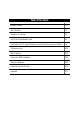
Table Of Content Revision History P.1 Item Checklist P.2 Summary of Features P.3 6VX7B-4X Motherboard Layout P.5 Page Index for CPU Speed Setup/Connectors/Panel and Jumper Definition P.6 Performance List P.34 Block Diagram P.35 Suspend to RAM Installation P.36 Memory Installation P.42 Page Index for BIOS Setup P.43 Appendix P.
6VX7B-4X Motherboard Revision History Revision 3.2 3.2 Revision Note Initial release of the 6VX7B-4X motherboard user’s manual. Second release of the 6VX7B-4X motherboard user’s manual. Date Sep.2000 Jun.2001 The author assumes no responsibility for any errors or omissions that may appear in this document nor does the author make a commitment to update the information contained herein. Third-party brands and names are the property of their respective owners. Jun. 27, 2001 Taipei, Taiwan, R.O.
Item Checklist Item Checklist ;The 6VX7B-4X motherboard ;Cable for IDE / floppy device ;Diskettes or CD (TUCD) for motherboard driver & utility ;6VX7B-4X user’s manual 2
6VX7B-4X Motherboard Summary Of Features Form Factor CPU Chipset Clock Generator Memory I/O Control Slots On-Board IDE On-Board Peripherals y 30.4 cm x 20.3 cm ATX Size form factor, 4 layers PCB.
Summary of Features Hardware Monitor PS/2 Connector BIOS On-Board Sound Additional Features y y y y y y y y y y y y y y CPU / System fan revolution detect CPU / System temperature detect System voltage detect CPU overheat shutdown detect PS/2 keyboard interface and PS/2 mouse interface Licensed AMI BIOS, 2M bit flash ROM Build –in VIA sound (VIA VT82C686B) Creative CT5880 sound (Optional) Supports Wake-on-LAN (WOL) Supports Internal / External modem wake up Includes 3 fan power connectors
6VX7B-4X Motherboard 6VX7B-4X Motherboard Layout JP30 PS/2 JP16 JP5 USB1 LED1 JP9 LPT PGA 370 CPU JP11 Floppy ATX Power COMA JP19 COMB JP15 IDE2 IDE1 VT82C694X J7 J5 AMR Front USB DIMM3 6VX7B-4X JP18 DIMM2 SW1 J8 DIMM1 GAME & AUDIO SW2 J11 BAT1 JP8 JP7 JP23 AGP JP1 PCI1 USB2 PCI2 J1 Creative CT5880 J3 VT82C686B PCI3 JP2 PCI4 BZ1 J4 JP20 BIOS PCI5 JP22 ISA J12 JP24 J2 5
6VX7B-4X Motherboard Layout Page Index for CPU Speed Setup/Connectors/Panel and Jumper Definition CPU Speed Setup Connectors Game & Audio Port COM A / COM B / LPT Port USB1 Connector PS/2 Keyboard & PS/2 Mouse Connector JP16 (CPU Fan) JP15 (Power Fan) JP2 (System Fan) ATX Power USB 2 Connector IR Connector Floppy Port IDE 1(Primary)/ IDE 2(Secondary) Port J3 (Ring Power On) J1 (Wake on LAN) J7 (TEL) J5 (AUX_IN) J8 (CD Audio Line In) JP5 (STR LED Connector) & LED 1 (DIMM LED) Front USB Port (Optional) J11
6VX7B-4X Motherboard CPU Speed Setup The system bus speed is selectable at 66,100,133MHz and Auto. The user can select the system bus speed (SW1) and change the DIP switch (SW2) selection to set up the CPU speed for 500MHz – 1GHz processor. SW1: O: ON, X: OFF CPU PCI CLK 1 2 3 4 5 6 Auto 33.3 X X X X O O 66 33.3 O O X X X X 75 37.5 O O O X X X 83 41.6 O O X O X X 100 33.3 O X X X X X X 112 37.3 O X O X X 124 31 X X X O X X 133 33.
CPU Speed Setup X14 X15 X16 O X O O O X O O O X X X ) For Auto Jumper setting: ON 1 2 3 4 5 6 SW1 Note: 1. If you use 66, 100, 133 MHz CPU, we recommend you to set up your system speed to “Auto” value. 2. We don’t recommend you to set up your system speed to 75,83,112, 124, 140,150 MHz because these frequencies are not the standard specifications for CPU, Chipset and most of the peripherals.
6VX7B-4X Motherboard 2. Celeron TM 566 / 66 MHz FSB ON 1 2 3 4 SW2 3. Celeron TM 600 / 66 MHz FSB ON 1 2 3 4 SW2 4.
CPU Speed Setup 5. Celeron TM 667 / 66 MHz FSB ON 1 2 3 4 SW2 6. 1 2 3 4 5 6 SW1 Celeron TM 700 / 66 MHz FSB ON 1 2 3 4 SW2 7.
6VX7B-4X Motherboard 8. Cyrix® III 533 / 133 MHz FSB (Optional) ON 1 2 3 4 SW2 9. ON 1 2 3 4 5 6 SW1 Cyrix® III 600 / 133 MHz FSB (Optional) ON 1 2 3 4 SW2 ON 1 2 3 4 5 6 SW1 10.
CPU Speed Setup 11. Pentium® !!! 550 / 100MHz FSB ON 1 2 3 4 SW2 ON 1 2 3 4 5 6 SW1 12. Pentium® !!! 600 / 100MHz FSB ON 1 2 3 4 SW2 ON 1 2 3 4 5 6 SW1 13.
6VX7B-4X Motherboard 14. Pentium® !!! 700 / 100MHz FSB ON ON 1 2 3 4 5 SW2 6 SW1 ® 15. Pentium !!! 750 / 100MHz FSB 1 2 3 4 ON 1 2 3 4 SW2 ON 1 2 3 4 5 6 SW1 16.
CPU Speed Setup 17. Pentium® !!! 850 / 100MHz FSB ON 1 2 3 4 SW2 ON 1 2 3 4 5 6 SW1 18. Pentium® !!! 533 / 133MHz FSB ON 1 2 3 4 SW2 ON 1 2 3 4 5 6 SW1 19.
6VX7B-4X Motherboard 20. Pentium® !!! 667 / 133MHz FSB ON 1 2 3 4 SW2 ON 1 2 3 4 5 6 SW1 21. Pentium® !!! 733 / 133MHz FSB ON 1 2 3 4 SW2 ON 1 2 3 4 5 6 SW1 22.
CPU Speed Setup 23. Pentium® !!! 866 / 133MHz FSB ON ON 1 2 3 4 1 2 3 4 5 SW2 6 SW1 ® 24. Pentium !!! 933 / 133MHz FSB ON 1 2 3 4 SW2 ON 1 2 3 4 5 6 SW1 25.
6VX7B-4X Motherboard Connectors Game & Audio Port Game Port MIC In Line Out Line In COM A / COM B / LPT Port LPT Port COM A 17 COM B
Connectors USB 1 Connector Pin No. 1 2 3 4 5 6 7 8 1 2 3 4 5 67 8 Definition USB V0 USB D0USB D0+ GND USB V1 USB D1USB D1+ GND PS/2 Keyboard & PS/2 Mouse Connector PS/2 Mouse 5 6 4 3 2 1 PS/2 Keyboard PS/2 Mouse/ Keyboard Pin No.
6VX7B-4X Motherboard JP16: CPU Fan 1 Pin No. Definition 1 GND 2 +12V 3 SENSE JP15: Power Fan 1 Pin No.
Connectors JP2: System Fan 1 Pin No. Definition 1 GND 2 +12V 3 SENSE ATX Power Pin No. Definition 3,5,7,13,15-17 GND 1,2,11 3.
6VX7B-4X Motherboard USB 2 Connector 5 4 8 1 Pin No. 1 2 3 4 5 6 7 8 Definition VCC USB D0USB D0+ GND VCC USB D1USB D1+ GND IR Connector 1 PIN No.
Connectors Floppy Port Red Line IDE1 (Primary), IDE2(Secondary) Port Red Line 6 IDE 1 IDE 2 22
6VX7B-4X Motherboard J3: Ring Power On (Internal Modem Card Wake Up) 1 Pin No. 1 2 Definition Signal GND J1: Wake On LAN 1 Pin No.
Connectors J7: TEL: The connector is for Modem with internal voice connector 1 Pin No. Definition 1 Signal-In 2 GND 3 GND 4 Signal-Out J5: AUX_IN 1 Pin No.
6VX7B-4X Motherboard J8: CD Audio Line In 1 Pin No.
Connectors Front USB Port (Optional) 10 9 2 1 Pin No. 1,4,5,10 2 3,7,9 6 8 Definition NC +5V GND USBP0+ USBP0- J11: SM BUS 1 Pin No.
6VX7B-4X Motherboard Panel And Jumper Definition 1 SPK 1 1 1 GD RE PW P+ P− P− HD GN J2: For 2x11 Pins Jumper GN (Green Switch) GD (Green LED) HD (IDE Hard Disk Active LED) SPKR (Speaker Connector) RE (Reset Switch) P+P−P−(Power LED) PW (Soft Power Connector) 1 Open: Normal Operation Close: Entering Green Mode Pin 1: LED anode(+) Pin 2: LED cathode(−) Pin 1: LED anode(+) Pin 2: LED cathode(−) Pin 1: VCC(+) Pin 2- Pin 3: NC Pin 4: Data(−) Open: Normal Operation Close: Reset Hardware System Pin
Panel and Jumper Definition JP1: Clear CMOS Function 1 Pin No.
6VX7B-4X Motherboard JP11: STR Enable 1 Pin No. Definition Open STR Disabled (Default) Close STR Enabled JP20: Onboard Sound Function Selection (Optional) 1 6 Pin No.
Panel and Jumper Definition JP24: Normal/ Recovery mode (Optional) 1 Pin No. Open Close Definition Normal Recovery JP19: Cyrix CPU Turbo Function (Optional) 1 Pin No.
6VX7B-4X Motherboard JP9: USB Device Wake up Selection 1 Pin No. Definition 1-2 close Normal (Default) Enabled USB Device 2-3 close Wake up (If you want to use “USB KB Wakeup from S3~S5” function, you have to set the BIOS setting “USB KB Wakeup from S3~S5” enabled, and the jumper “JP9” enabled). *(Power on the computer and as soon as memory counting starts, press . You will enter BIOS Setup. Select the item “POWER MANAGEMENT SETUP”, then select “USB KB Wakeup from S3~S5: Enabled”.
Panel and Jumper Definition JP22: BIOS Flash ROM Write Protect 1 Pin No. Close Open Definition BIOS Write Disabled BIOS Write Enabled (Default) 0Please set Jumper JP22 to “Open” to enabled BIOS write function when you update new BIOS or new device. JP30: Over Voltage CPU Speed Up (Magic Booster) (Optional) (When JP30 set “7-8 Close”, CPU Voltage is rising 10%) 2 1 Pin No.
6VX7B-4X Motherboard J12: Front Panel Jumper (Optional) 1 2 15 16 Pin No. Definition 1 HD LED+ 2 GN LED+ 3 HD LED4 PWR LED+ 5,7 RESET SW 6,8 Soft ON/OFF 10,12 Green SW 9 +5V 11 IR RX 13 GND 15 IRTX 14 NC 16 IR Power BAT1: Battery + ☞ Danger of explosion if battery is incorrectly replaced. ☞ Replace only with the same or equivalent type recommended by the manufacturer. ☞ Dispose of used batteries according to the manufacturer’s instructions.
Performance List Performance List The following performance data list is the testing results of some popular benchmark testing programs. These data are just referred by users, and there is no responsibility for different testing data values gotten by users. (The different Hardware & Software configuration will result in different benchmark testing results.
6VX7B-4X Motherboard Block Diagram 14.318MHz AGP 2X/4X PGA 370 CPU 3.3V DIMM DIMM Sockets 66 /100/133 MHz Ultra DMA 33/ATA66 IDE Ports 66 /100 /133 MHz VIA VT82C694X AGP Bus 33 MHz 66 /100 /133 MHz Host Bus ICS 9248DF-39 PCI Bus 33 MHz ISA Bus VIA VT82C686B Creative CT5880 AC’97-Link COM Ports USB Bus IDE Bus 24MHz 48MHz 14.
Suspend to RAM Installation Suspend To RAM Installation A.1 Introduce STR function: Suspend-to-RAM (STR) is a Windows 98 ACPI sleep mode function. When recovering from STR (S3) sleep mode, the system is able, in just a few seconds, to retrieve the last “state” of the system before it went to sleep and recover to that state. The “state” is stored in memory (RAM) before the system goes to sleep.
6VX7B-4X Motherboard Step 2: (If you want to use STR Function, please set jumper JP11 Closed.) 1 Pin No. Definition Open STR Disabled (Default) Close STR Enabled Step 3: Power on the computer and as soon as memory counting starts, press . You will enter BIOS Setup. Select the item “POWER MANAGEMENT SETUP”, then select “ACPI Sleep Type: S3 / STR”. Remember to save the settings by pressing "ESC" and choose the “SAVE & EXIT SETUP” option.
Suspend to RAM Installation A.3 How to put your system into STR mode? 1. There are two ways to accomplish this: Choose the “Stand by” item in the “Shut Down Windows” area. A. Press the “Start” button and then select “Shut Down” B.
6VX7B-4X Motherboard 2. Define the system ”power on” button to initiate STR sleep mode: A. Double click “My Computer” and then “Control Panel” B. Double click the “ Power Management” item.
Suspend to RAM Installation C. Select the “Advanced” tab and “Standby” mode in Power Buttons. Step 4: Restart your computer to complete setup. Now when you want to enter STR sleep mode, just momentarily press the “Power on” button.. A.4 How to recover from the STR sleep mode? There are five ways to “wake up” the system: 1. 2. 3. 4. 5. Press the “Power On” button. Use the “Resume by Alarm” function. Use the “Modem Ring On” function. Use the “Wake On LAN” function. Use the “USB Device Wake up” function.
6VX7B-4X Motherboard A.5 Notices: 1. In order for STR to function properly, several hardware and software requirements must be satisfied: A. B. 2. Your ATX power supply must comply with the ATX 2.01 specification (provide more than 720 mA 5V Stand-By current). Your SDRAM must be PC-100 compliant. Jumper JP5 is provided to connect to the STR LED in your system chassis. [Your chassis may not provide this feature.] The STR LED will be illuminated when your system is in STR sleep mode.
Memory Installation Memory Installation The motherboard has 3 dual inline memory module (DIMM) sockets. The BIOS will automatically detects memory type and size. To install the memory module, just push it vertically into the DIMM Slot .The DIMM module can only fit in one direction due to the two notch. Memory size can vary between sockets.
6VX7B-4X Motherboard Page Index for BIOS Setup The Main Menu Standard CMOS Setup BIOS Features Setup Chipset Features Setup Power Management Setup PNP/ PCI Configuration Load BIOS Defaults Load Setup Defaults Integrated Peripherals Hardware Monitor Setup Supervisor Password / User Password IDE HDD Auto Detection Save & Exit Setup Exit Without Saving Page P.45 P.47 P.50 P.52 P.55 P.58 P.60 P.61 P.62 P.66 P.68 P.69 P.70 P.
BIOS Setup BIOS Setup BIOS Setup is an overview of the BIOS Setup Program. The program that allows users to modify the basic system configuration. This type of information is stored in battery-backed CMOS RAM so that it retains the Setup information when the power is turned off. ENTERING SETUP Power ON the computer and press immediately will allow you to enter Setup.
6VX7B-4X Motherboard GETTING HELP Main Menu The on-line description of the highlighted setup function is displayed at the bottom of the screen. Status Page Setup Menu / Option Page Setup Menu Press F1 to pop up a small help window that describes the appropriate keys to use and the possible selections for the highlighted item. To exit the Help Window press . The Main Menu Once you enter AMI BIOS CMOS Setup Utility, the Main Menu (Figure 1) will appear on the screen.
BIOS Setup • Chipset Features Setup This setup page includes all the items of chipset special features. • Power Management Setup This setup page includes all the items of Green function features. • PnP/PCI Configurations This setup page includes all the configurations of PCI & PnP ISA resources. • Load BIOS Defaults Bios Defaults indicates the value of the system parameter which the system would be in the safe configuration.
6VX7B-4X Motherboard Standard CMOS Setup The items in Standard CMOS Features Menu (Figure 2) are divided into 9 categories. Each category includes no, one or more than one setup items. Use the arrows to highlight the item and then use the or keys to select the value you want in each item. AMIBIOS SETUP – STANDARD CMOS SETUP ( C ) 1999 American Megatrends, Inc.
BIOS Setup • Time The times format in . The time is calculated base on the 24-hour military-time clock. For example, 1 p.m. is 13:00:00. • Primary Master, Slave / Secondary Master, Slave The category identifies the types of hard disk from drive C to F that has been installed in the computer. There are two types: auto type, and user definable type. User type is user-definable; Auto type which will automatically detect HDD type.
6VX7B-4X Motherboard • Boot Sector Virus Protection If it is set to enable, the category will flash on the screen when there is any attempt to write to the boot sector or partition table of the hard disk drive. The system will halt and the following error message will appear in the mean time. You can run anti-virus program to locate the problem.
BIOS Setup BIOS Features Setup AMIBIOS SETUP – BIOS FEATURES CMOS SETUP ( C ) 1999 American Megatrends, Inc. All Rights Reserved 1st Boot Device 2nd Boot Device 3rd Boot Device S.M.A.R.
6VX7B-4X Motherboard • Boot Up Num-Lock On Off Keypad is number keys. (Default Value) Keypad is arrow keys. • Floppy Drive Seek During POST, BIOS will determine if the floppy disk drive installed is 40 or 80 tracks. 360 type is 40 tracks while 720 , 1.2 and 1.44 are all 80 tracks. Enabled Disabled BIOS searches for floppy disk drive to determine if it is 40 or 80 tracks. Note that BIOS can not tell from 720, 1.2 or 1.44 drive type as they are all 80 tracks.
BIOS Setup Chipset Features Setup AMIBIOS SETUP –CHIPSET FEATURE CMOS SETUP ( C ) 1999 American Megatrends, Inc. All Rights Reserved *** DRAM Timing *** Top Performance SDRAM Timing by SPD SDRAM CAS# Latency DRAM Frequency :Disabled :Disabled :3 :Auto C2P Concurrency & Master DRAM Integrity Mode AGP Mode AGP Comp. Driving Manual AGP Comp. Driving AGP Aperture Size ClkGen Spread Spectrum USB Controller USB Legacy Support :Enabled :Disabled :4X :Auto :CB :64MB :Center± 0.
6VX7B-4X Motherboard • C2P Concurrency & Master Enabled Disabled Enabled C2P Concurrency & Master. (Default Value) Disabled C2P Concurrency & Master. • DRAM Integrity Mode ECC Disabled For 72 bit ECC type DIMM Modle. Normal Setting. (Default Value) • AGP Mode 4X 1X 2X Set AGP Mode is 4X. (Default Value) Set AGP Mode is 1X. Set AGP Mode is 2X. • AGP Comp. Driving Auto Manual Set AGP Comp. Driving is Auto. (Default Value) Set AGP Comp. Driving is Manual. If AGP Comp. Driving is Manual.
BIOS Setup • USB Controller USB Port 0&1 USB Port 2&3 All USB Port Disabled USB Controller for USB Port 0&1. USB Controller for USB Port 2&3. USB Controller for All USB Port. (Default Value) USB Controller Function Disabled. • USB Legacy Support Keyboard Keyb+Mouse Disabled Set USB Legacy Support Keyboard. Set USB Legacy Support Keyboard +Mouse. Disabled USB Legacy Support Function.
6VX7B-4X Motherboard Power Management Setup AMIBIOS SETUP –POWER MANAGEMENT SETUP ( C ) 1999 American Megatrends, Inc.
BIOS Setup • Suspend Time Out (Minute.) Disabled Suspend Time Out Function. (Default Value) Enabled Suspend Time Out after 1min. Enabled Suspend Time Out after 2min. Enabled Suspend Time Out after 4min. Enabled Suspend Time Out after 8min. Enabled Suspend Time Out after 10min. Enabled Suspend Time Out after 20min. Enabled Suspend Time Out after 30min. Enabled Suspend Time Out after 40min. Enabled Suspend Time Out after 50min. Enabled Suspend Time Out after 60min.
6VX7B-4X Motherboard • MODEM Use IRQ NA 3 4 5 7 Set MODEM Use IRQ to NA. Set MODEM Use IRQ to 3. Set MODEM Use IRQ to 4. (Default Value) Set MODEM Use IRQ to 5. Set MODEM Use IRQ to 7. • Modem Ring On/Wake On Lan Disabled Enabled Disabled Modem Ring On/Wake On Lan. Enabled Modem Ring On/Wake On Lan. (Default Value) • PME Event Wake up Disabled Enabled Disabled PME Event Wake up function. Enabled PME Event Wake up function.
BIOS Setup PnP/PCI Configurations AMIBIOS SETUP –PNP/PCI CONFIGURATION SETUP ( C ) 1999 American Megatrends, Inc.
6VX7B-4X Motherboard • DMA Channel (0,1,3,5,6,7) PnP ISA / EISA The resource is used by PnP device. The resource is used by ISA / EISA device (PCI or ISA). • IRQ (3,4,5,7, 9,10,11,14,15) PCI/PnP ISA / EISA The resource is used by PCI/PnP device. The resource is used by ISA / EISA device (PCI or ISA).
BIOS Setup Load BIOS Defaults AMIBIOS SIMPLE SETUP UTILITY-VERSION 1.23 ( C ) 1999 American Megatrends, Inc.
6VX7B-4X Motherboard Load Setup Defaults AMIBIOS SIMPLE SETUP UTILITY-VERSION 1.23 ( C ) 1999 American Megatrends, Inc.
BIOS Setup Integrated Peripherals AMIBIOS SETUP –INTEGRATED PERIPHERAL ( C ) 1999 American Megatrends, Inc.
6VX7B-4X Motherboard • OnBoard Serial Port 2 Auto 3F8/COM1 2F8/COM2 3E8/COM3 2E8/COM4 Disabled • BIOS will automatically setup the port 2 address. (Default Value) Enable onBoard Serial port 2 and address is 3F8. Enable onBoard Serial port 2 and address is 2F8. Enable onBoard Serial port 2 and address is 3E8. Enable onBoard Serial port 2 and address is 2E8. Disable onBoard Serial port 2.
BIOS Setup • Parallel Port IRQ 7 Auto 5 • OnBoard AC’97 Audio Auto Disabled • Enabled Sound Blaster. Disabled Sound Blaster. (Default Value) SB I/O Base Address 220h-22Fh 280h-28Fh 260h-26Fh 240h-24Fh • Enabled OnBoard Legacy Audio. (Default Value) Disabled OnBoard Legacy Audio. Sound Blaster Enabled Disabled • Set OnBoard MC’97 Modem to Auto. (Default Value) Disabled OnBoard MC’97 Modem. OnBoard Legacy Audio Enabled Disabled • Set OnBoard AC’97 Audio to Auto.
6VX7B-4X Motherboard • MUP-401 I/O Address 330h-333h 300h-303h 310h-313h 320h-323h • FM Port (388h-38Bh) Disabled Enabled • Set MUP-401 I/O Address is 330h-333h. (Default Value) Set MUP-401 I/O Address is 300h-303h. Set MUP-401 I/O Address is 310h-313h. Set MUP-401 I/O Address is 320h-323h. Disabled FM Port (388h-38Bh). (Default Value) Enabled FM Port (388h-38Bh). Game Port (200h-207h) Disabled Enabled Disabled Game Port (200h-207h). Enabled Game Port (200h-207h).
BIOS Setup Hardware Monitor AMIBIOS SETUP –HARDWARE MONITOR ( C ) 1999 American Megatrends, Inc. All Rights Reserved ACPI Shut Down Temp. :Disabled Current CPU Temp. :36°C/96°F Current System Temp. :28°C/82°F Case Status :Closed Current CPU Fan Speed :5487 RPM Current System Fan Speed :0 RPM Vcore :1.634V +3.300V :3.590V +5.000V :5.119V +12.000V :11.
6VX7B-4X Motherboard • Current CPU Temp. (°°C / °F) Detect CPU Temperature automatically. • Current System Temp. (°°C / °F) Detect System Temperature automatically. • Case Status If the case is closed, “Case Status” will show “Closed”. If the case have been opened, “Case Opened” will show “Open”. • Current CPU Fan Speed Detect CPU Fan speed status automatically . • Current System Fan Speed Detect System Fan speed status automatically . • Current Voltage (V) VCORE / +3.
BIOS Setup Set Supervisor / User Password When you select this function, the following message will appear at the center of the screen to assist you in creating a password. AMIBIOS SIMPLE SETUP UTILITY-VERSION 1.23 ( C ) 1999 American Megatrends, Inc.
6VX7B-4X Motherboard IDE HDD AUTO Detection AMIBIOS SETUP – STANDARD CMOS SETUP ( C ) 1999 American Megatrends, Inc. All Rights Reserved Date (mm/dd/yyyy) : Tue Feb 17, 2000 Time (hh/mm/ss) : 10:36:24 TYPE SIZE CYLS HEAD PRECOMP LANDZ SECTOR MODE Pri Master :Auto Pri Slave :Auto Sec Master :Auto Sec Slave :Auto Floppy Drive A: 1.
BIOS Setup Save & Exit Setup AMIBIOS SIMPLE SETUP UTILITY-VERSION 1.23 ( C ) 1999 American Megatrends, Inc.
6VX7B-4X Motherboard Exit Without Saving AMIBIOS SIMPLE SETUP UTILITY-VERSION 1.23 ( C ) 1999 American Megatrends, Inc.
Appendix Appendix Appendix A : VIA Chipsets Driver Installation A.VIA 4 in 1 Service Pack Utility: Insert the support CD that came with your motherboard into your CD-ROM driver or double –click the CD driver icon in My Computer to bring up the screen. 1.Click “VIA 4in 1 Service Pack Utility” item. 2.Click “Next”. (1) (2) 4.Click “Next”. 3.Click “Yes”. (4) (3) 5.Click “Next”. 6.Click “Next”.
6VX7B-4X Motherboard 8.Click “Next”. 7.Click “Next”. (8) (7) 10.Click “Finish” to restart computer. 9.Click “Next”.
Appendix Appendix B: VIA Sound Driver A. AC’97 Audio Driver: Insert the support CD that came with your motherboard into your CD-ROM driver or double –click the CD driver icon in My Computer to bring up the screen. Audio 2.Click “Next”. 1.Click “AC’97 Audio Driver” item. (2) (1) 4.Click “Finish” to restart. 3.
6VX7B-4X Motherboard Appendix C: Creative Sound Driver Installation (Optional) Insert the support CD that came with your motherboard into your CD-ROM driver or double –click the CD driver icon in My Computer to bring up the screen. Audio 2.Click “OK”. 1.Click “Creative 5880 Sound Driver”. (2) (1) 4.Click “Next”. 3.Click “Yes”. (4) (3) 6.Click here. 5.Click “Next”.
Appendix 7.Click “Finish” to restart computer.
6VX7B-4X Motherboard Appendix D: BIOS Flash Procedure BIOS update procedure: 9 Please check your BIOS vendor (AMI or AWARD) on the motherboard. 9 It is recommended you copy the AWDFlash.exe or AMIFlash.exe in driver CD (D:\>Utility\BIOSFlash) and the BIOS binary files into the directory you made in your hard disk.【i.e:C:\>Utility\ (C:\>Utility : denotes the driver and the directory where you put the flash utilities and BIOS file in.
Appendix Appendix E: Acronyms Acro. ACPI POST LAN ECP APM DMA MHz ESCD CPU SMP USB OS ECC IDE SCI LBA EMC BIOS SMI IRQ NIC A.G.P. S.E.C.C.
6VX7B-4X Motherboard Acro.