The author assumes no responsibility for any errors or omissions that may appear in this document nor does the author make a commitment to up date the information contained herein. Third-party brands and names are the property of their respective owners. Please do not remove any labels on motherboard, this may void the warranty of this motherboard. Due to rapid change in technology, some of the specifications might be out of date before pwblicution of this booklet.
GA-7VTXE/GA-7VTXH AMD Socket A Processor Motherboard USER’S MANUAL AMD Athlon™/ Athlon™ XP / Duron™ Socket A Processor Motherboard Rev. 1.
GA-7VTXE/GA-7VTXH Motherboard Table of Content Revision History..................................................................................... 6 Item Checklist ......................................................................................... 6 WARNING! ............................................................................................... 7 Chapter 1 Introduction ............................................................................. 8 Summary of Features .......................
Table of Content PNP/PCI Configuration .............................................................................. 39 Load Fail-Safe Defaults ............................................................................. 41 Load Optimized Defaults ........................................................................... 42 Integrated Peripherals ............................................................................... 43 Hardware Monitor & MISC Setup ..............................................
GA-7VTXE/GA-7VTXH Motherboard Revision History Revision Revision Note 1.0 Initial release of the GA-7VTXE/GA-7VTXH motherboard user's manual. 1.0 Date Sep.2001 Second release of the GA-7VTXE/GA-7VTXH motherboard user's manual. Oct .
WARNING! WARNING! Computer motherboards and expansion cards contain very delicate Integrated Circuit (IC) chips. To protect them against damage from static electricity, you should follow some precautions whenever you work on your computer. 1. Unplug your computer when working on the inside. 2. Use a grounded wrist strap before handling computer components. If you do not have one, touch both of your hands to a safely grounded object or to a metal object, such as 3. the power supply case.
GA-7VTXE/GA-7VTXH Motherboard Chapter 1 Introduction Summary of Features Form Factor 30.4cm x 20.5cm ATX size form factor, 4 layers PCB. Motherboard CPU GA-7VTXE/GA-7VTXH Motherboard Socket A processor AMD AthlonTM/AthlonTM XP/ DuronTM (K7) 128K L1 & 256K/64K L2 cache on die 200/266MHz FSB and DDR bus speeds (PCI 33MHz) Supports 1.
Introduction Creative CT5880 Sound Chip* AC97 CODEC On-Board LAN Line In/Line Out/Mic In/CD In/Game Port Build in RTL8100L Chipset* PS/2 Connector BIOS PS/2 Keyboard interface and PS/2 Mouse interace Licensed AMI BIOS, 2M bit Flash ROM Additional Features Support Dual BIOS STR(Suspend-To-RAM) Wake on LAN** AC Recovery USB KB/Mouse wake up from S3 Supports @BIOSTM Supports Easy TuneIIITM On-Board Sound Please set the CPU host frequency in accordance with your pr
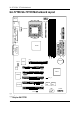
GA-7VTXE/GA-7VTXH Motherboard GA-7VTXE/GA-7VTXH Motherboard Layout MS_KB LPT COMA CK_RATIO* KT266A AGP CD_IN IDE1 BATTERY IT8705 PCI1 AC97 PCI2 VT8233 CT5880* IR PCI3 CLK_JP PCI4 RTL8100* PCI5 MAIN BIOS Backup BIOS USB1 WOL** "*" Only for GA-7VTXH. "**" Only for GA-7VTXE.
Hardware Installation Process Chapter 2 Hardware Installation Process To set up your computer, you must complete the following setups: Step 1- Set Dip Switch (CK_RATIO)* and system Jumper(CLK_JP) Step 2- Install the Central Processing Unit (CPU) Step 3- Install memory modules Step 4- Install expansion cards Step 5- Connect ribbon cables, cabinet wires, and power supply Step 6- Setup BIOS software Step 7- Install supporting software tools Step 1* Step 2 Step 3 Step 5 Step 5 Step 5 Step 4 Step 1 Step 5
GA-7VTXE/GA-7VTXH Motherboard Step 1: Install the Central Processing Unit (CPU) Step1-1: CPU Speed Setup The clock ratio can be switched by CK_RATIO and refer to below table. O: ON / X :OFF ON 1 2 3 4 5 RATIO 1 2 3 4 5 AUTO(Default) X 5x O X O X X X O O X 5.5x 6x X O O X X X O O X X 6.5x 7x X O X O X O O X X X 7.5x 8x X O O X O O X X X X 8.5x 9x X O X O O X X X X X 9.5x 10x X O O X X X X X X X 10.5x 11x X O X O X O X O X X 11.
Hardware Installation Process Step1-2: CPU Installation CPU Top View CPU Bottom View Socket Actuation Lever Pin1 indicator 2. Locate Pin 1 in the socket and look 1. Pull up the CPU socket level and up to 90-degree angle. for a (golden) cut edge on the CPU upper corner. Then insert the CPU into the socket. Please make sure the CPU type is supported by the motherboard. If you do not match the CPU socket Pin 1 and CPU cut edge well, it will cause improper installation.
GA-7VTXE/GA-7VTXH Motherboard Step1-3:CPU Heat Sink Installation 1. Press down the CPU socket lever and finish CPU installation. 2. Use qualified fan approved by AMD. 3. Fasten the heatsink supporting-base onto the CPU socket on the main- 4. Make sure the CPU fan is plugged to the CPU fan connector, board. than install complete. Please use AMD approved cooling fan. We recommend you to apply the thermal paste to provide better heat conduction between your CPU and heatsink.
Hardware Installation Process Step 2: Install memory modules The motherboard has 3 dual inline memory module (DIMM) sockets. The BIOS will automatically detects memory type and size. To install the memory module, just push it vertically into the DIMM Slot. The DIMM module can only fit in one direction due to the notch. Memory size can vary between sockets.
GA-7VTXE/GA-7VTXH Motherboard DDR 1. The DIMM slot has a notch, so the DIMM memory module can only fit in one direction. 2. Insert the DIMM memory module verticallyinto the DIMM slot. Then push it down. 3. Close the plastic clip at both edges of theDIMM slots to lock the DIMM module. Reverse the installation steps when you wish to remove the DIMM module.
Hardware Installation Process Step 3: Install expension cards 1. Read the related expansion card’s instruction document before install the expansion card into the computer. 2. Remove your computer’s chassis cover, necessary screws and slot bracket from the computer. 3. Press the expansion card firmly into expansion slot in motherboard. 4. Be sure the metal contacts on the card are indeed seated in the slot. 5. Replace the screw to secure the slot bracket of the expansion card. 6.
GA-7VTXE/GA-7VTXH Motherboard Step 4: Connect ribbon cables, cabinet wires, and power supply Step4-1:I/O Back Panel Introduction PS/2 Keyboard and PS/2 Mouse Connector PS/2 Mouse Connector (6 pin Female) This connector supports standard PS/2 keyboard and PS/2 mouse. PS/2 Keyboard Connector (6 pin Female) USB & LAN Connector Before you connect your device(s) into USB LAN* connector(s), please make sure your device(s) such as USB keyboard,mouse, scanner, zip, USB 0 speaker..etc.
Hardware Installation Process Parallel Port , Serial Ports (COMA / COMB) Parallel Port (25 pin Female) This connector supports 2 standard COM ports ,1 Parallel port . Device like printer can be con nected to Parallel port ; mouse and modem etc can be connected to Serial ports. COMA COMB Serial Port (9 pin Male) Game /MIDI Ports This connector supports joystick, MIDI keyboard and other relate audio devices.
GA-7VTXE/GA-7VTXH Motherboard Step4-2: Connectors Introduction AB C D E J I F G H** A) B) C) D) E) CPU FAN SYS FAN ATX Floppy/IDE1/IDE2 Battery F) G) H) I) J) "**" Only for GA-7VTXE.
Hardware Installation Process A) CPU_FAN (CPU_FAN Connector) B) SYS_FAN (SYS_FAN Connector) 1 GND +12V/Control Sense GND +12V/Control Sense 1 The CPU fan connector supports Max. current up to 600 mA . C) ATX (ATX Power) 20 +12V 5V SB (Stand by +5V) Power Good GND VCC GND VCC GND 3.3V 3.3V VCC VCC -5V GND GND GND PS-ON(Soft On/Off) GND -12V 3.
GA-7VTXE/GA-7VTXH Motherboard I) IR GND NC USB D3+ USB D3Power G) USB1 GND IRTX NC IRRX VCC 1 Be careful with the polarity of the IR connector while you connect the IR. Please contact you Power USB D2USB D2+ NC GND nearest dealer for optional IR device. Be careful with the polarity of the front panel USB connector. Check the pin assignment while you connect the front panel USB cable. Please contact your nearest dealer for optional front panel USB cable.
Hardware Installation Process RST+ RST- SPK+ 1 SPK- HD- F) F_PANEL (2x7 pins jumper) 14 1 13 HD+ 1 PD_Y PD_G PD+ PWPW+ 2 HD (IDE Hard Disk Active LED) Pin 1: LED anode(+) SPK (Speaker Connector) Pin 2: LED cathode(-) Pin 1: VCC(+) Pin 2- Pin 3: NC Pin 4: Data(-) RST (Reset Switch) Open: Normal Operation Close: Reset Hardware System PD+/PD_G/PD_Y(Power LED) Pin 1: LED anode(+) Pin 2: LED cathode(-) PW (Soft Power Connector) Pin 3: LED cathode(-) Open: Normal Operation Close: Power On/Off
GA-7VTXE/GA-7VTXH Motherboard Chapter 3 BIOS Setup BIOS Setup is an overview of the BIOS Setup Program. The program that allows users to modify the basic system configuration. This type of information is stored in battery-backed CMOS RAM so that it retains the Setup information when the power is turned off. ENTERINGSETUP Power ON the computer and press immediately will allow you to enter Setup.
BIOS Setup GETTINGHELP Main Menu The on-line description of the highlighted setup function is displayed at the bottom of the screen. Status Page Setup Menu / Option Page Setup Menu Press F1 to pop up a small help window that describes the appropriate keys to use and the possible selections for the highlighted item. To exit the Help Window press . The Main Menu (For example: BIOS Ver. :F3) Once you enter AMI BIOS CMOS Setup Utility, the Main Menu (Figure 1) will appear on the screen.
GA-7VTXE/GA-7VTXH Motherboard Power Management Setup This setup page includes all the adjustable items of Green function features. PNP/PCI Configurations This setup page includes all the adjustable configurations of PCI & PnP ISA resources. Load Fail-Safe Defaults Load Fail-Safe Defaults option loads preset system parameter values to set the system in its most stable configurations.
BIOS Setup Standard CMOS Features AMIBIOS SETUP - STANDARD CMOS SETUP ( C ) 1999 American Megatrends, Inc. All Rights Reserved Date (mm/dd/yyyy) : Fri Mar 16, 2001 Time (hh/mm/ss) : 14:44:35 TYPE SIZE CYLS HEAD PRECOMP LANDZ SECTOR MODE Pri Master : Auto Pri Slave : Auto Sec Master : Auto Sec Slave : Auto Floppy Drive A : 1.
GA-7VTXE/GA-7VTXH Motherboard Time The times format in . The time is calculated base on the 24-hour militarytime clock. For example, 1 p.m. is 13:00:00. Primary Master, Slave / Secondary Master, Slave The category identifies the types of hard disk from drive C to F that has been installed in the computer. There are two types: auto type, and manual type. Manual type is user-definable; Auto type which will automatically detect HDD type.
BIOS Setup Boot Sector Virus Protection If it is set to enable, the category will flash on the screen when there is any attempt to write to the boot sector or partition table of the hard disk drive. The system will halt and the following error message will appear in the mean time. You can run anti-virus program to locate the problem.
GA-7VTXE/GA-7VTXH Motherboard BIOS Features Setup AMIBIOS SETUP - BIOS FEATURES SETUP ( C ) 1999 American Megatrends, Inc. All Rights Reserved 1st Boot Device : Floppy 2nd Boot Device : IDE-0 3rd Boot Device : CDROM S.M.A.R.T.
BIOS Setup S.M.A.R.T. for Hard Disks Enabled Enable HDD S.M.A.R.T. Capability. Disabled Disable HDD S.M.A.R.T. Capability. (Default value) Boot Up Num-Lock On Keypad is number keys. (Default value) Off Keypad is arrow keys. Floppy Drive Seek During POST, BIOS will determine the floppy disk drive installed is 40 or 80 tracks. 360 K type is 40 tracks 720 K, 1.2 M and 1.44 M are all 80 tracks. Enabled BIOS searches for floppy disk drive to determine it is 40 or 80 tracks.
GA-7VTXE/GA-7VTXH Motherboard Chipset Features Setup AMIBIOS SETUP - CHIPSET FEATURES SETUP ( C ) 1999 American Megatrends, Inc. All Rights Reserved Top Performance :Disabled Configure SDRAM by SPD :Enabled DRAM Frequency :100 SDRAM CAS# Latency :2 SDRAM Command Rate :2T Command AGP Mode :4X AGP Comp. Driving :Auto Manual AGP Comp.
BIOS Setup DRAM Frequency 100MHz 133MHz Set DRAM Frequency is 100MHz. (Default Value). Set DRAM Frequency is 133MHz. Auto Set DRAM Frequency is Auto. SDRAM CAS# Latency 2 2.5 For Fastest SDRAM DIMM module. (Default Value). For Slower SDRAM DIMM module. SDRAM Command Rate 2T Command Set SDRAM Command Rate to 2T Command. (Default Value) 1T Command Set SDRAM Command Rate to 1T Command. AGP Mode 4X 1X Set AGP Mode is 4X. (Default Value) Set AGP Mode is 1X. 2X Set AGP Mode is 2X.
GA-7VTXE/GA-7VTXH Motherboard 32MB Set AGP Aperture Size to 32 MB. 64MB Set AGP Aperture Size to 64 MB. (Default Value) 128MB Set AGP Aperture Size to 128 MB. 256MB Set AGP Aperture Size to 256 MB. AGP Read Synchronization Enabled Enable AGP Read Synchronization. Disabled Disable AGP Read Synchronization. (Default Value) PCI Delay Transaction Enabled Disabled Enabled PCI Delay Transaction. (Default Value) Disabled PCI Delay Transaction.
BIOS Setup VCore Voltage Normal +5.0% Normal Function.(Default Value) Set VCore voltage to +5.0%. +7.5% +10.0% Set VCore voltage to +7.5%. Set VCore voltage to +10.0%.
GA-7VTXE/GA-7VTXH Motherboard Power Management Setup AMIBIOS SETUP - POWER MANAGEMENT SETUP ( C ) 1999 American Megatrends, Inc.
BIOS Setup Suspend Time Out (Minute.) Disabled Disabled Suspend Time Out Function. (Default Value) 1 Enabled Suspend Time Out after 1min. 2 Enabled Suspend Time Out after 2min. 4 Enabled Suspend Time Out after 4min. 8 Enabled Suspend Time Out after 8min. 10 Enabled Suspend Time Out after 10min. 20 Enabled Suspend Time Out after 20min. 30 Enabled Suspend Time Out after 30min. 40 Enabled Suspend Time Out after 40min. 50 Enabled Suspend Time Out after 50min.
GA-7VTXE/GA-7VTXH Motherboard Modem Ring On/Wake On LAN Disabled Disabled Resume On Ring / LAN. Enabled Enabled Resume On Ring / LAN. (Default Value) PME Event Wake Up Disabled Disable PME Event Wake Up. Enabled Enabled PME Event Wake Up. (Default Value) Keyboard Wakeup From S1(Suspend) Keyboard is able to Wakeup the system from S1(Suspend) state. (Default value) S1/S3 Keyboard is able to Wakeup the system from S1/S3 state.
BIOS Setup PNP/PCI Configuration AMIBIOS SETUP - PNP/PCI CONFIGURATION ( C ) 1999 American Megatrends, Inc.
GA-7VTXE/GA-7VTXH Motherboard 7 The system will reserved IRQ7 for PCI slot 1/5, 2, 3, 4 device if no legacy ISA device using IRQ7. 9 The system will reserved IRQ9 for PCI slot 1/5, 2, 3, 4 device if no legacy ISA device using IRQ9. 10 The system will reserved IRQ10 for PCI slot 1/5, 2, 3, 4 device if no legacy ISA device using IRQ10. 11 The system will reserved IRQ11 for PCI slot 1/5, 2, 3, 4 device if no legacy ISA device using IRQ11.
BIOS Setup Load Fail-Safe Defaults AMIBIOS SIMPLE SETUP UTILITY - VERSION 1.24e (C) 1999 American Megatrends, Inc.
GA-7VTXE/GA-7VTXH Motherboard Load Optimized Defaults AMIBIOS SIMPLE SETUP UTILITY - VERSION 1.24e (C) 1999 American Megatrends, Inc.
BIOS Setup Integrated Peripherals AMIBIOS SETUP - INTEGRATED PERIPHERALS ( C ) 1999 American Megatrends, Inc.
GA-7VTXE/GA-7VTXH Motherboard Onboard Serial Port 2 Auto BIOS will automatically setup the port 2 address (Default Value). 3F8/COM1 Enable onboard Serial port 2 and address is 3F8. 2F8/COM2 Enable onboard Serial port 2 and address is 2F8. 3E8/COM3 Enable onboard Serial port 2 and address is 3E8. 2E8/COM4 Enable onboard Serial port 2 and address is 2E8. Disabled Disable onboard Serial port 2. Serial Port 2 Mode Normal Normal operation.
BIOS Setup Parallel Port IRQ 7 Set Parallel Port IRQ is 7. Auto Set Auto to parallel Port IRQ DMA Channel. . (Default Value). 5 Set Parallel Port IRQ is 5. Parallel Port DMA Auto Set Auto to parallel port mode DMA Channel. . (Default Value). 3 Set Parallel Port DMA is 3. 1 Set Parallel Port DMA is 1. 0 Set Parallel Port DMA is 0. OnBoard IDE Disabled Disabled OnBoard IDE Both Set OnBoard IDE is Both (Default Value).
GA-7VTXE/GA-7VTXH Motherboard Hardware Monitor & MISC Setup AMIBIOS SETUP - HARDWARE MONITOR & MISC SETUP ( C ) 1999 American Megatrends, Inc. All Rights Reserved CPU Host Clock (Mhz) :By Jumper CPU Temp. : 35°C/ 95°F System Temp. : 33°C/ 91°F CPU Fan Speed : 5273 RPM System Fan Speed : 0 RPM Vcore : +1.632V Vtt : +3.344V +3.300V : +3.296V +5.000V : +5.080V ESC: Quit +12.000V : +11.840V F1 : Help 5V SB : +4.
BIOS Setup Set Supervisor / User Password When you select this function, the following message will appear at the center of the screen to assist you in creating a password. AMIBIOS SIMPLE SETUP UTILITY - VERSION 1.24e (C) 1999 American Megatrends, Inc.
GA-7VTXE/GA-7VTXH Motherboard IDE HDD Auto Detection AMIBIOS SETUP - STANDARD CMOS SETUP ( C ) 1999 American Megatrends, Inc. All Rights Reserved Date (mm/dd/yyyy) : Fri Mar 16, 2001 Time (hh/mm/ss) : 14:44:35 TYPE SIZE CYLS HEAD PRECOMP LANDZ SECTOR MODE Pri Master : Auto Pri Slave : Auto Sec Master : Auto Sec Slave : Auto Floppy Drive A : 1.
BIOS Setup Save & Exit Setup AMIBIOS SIMPLE SETUP UTILITY - VERSION 1.24e (C) 1999 American Megatrends, Inc.
GA-7VTXE/GA-7VTXH Motherboard Exit Without Saving AMIBIOS SIMPLE SETUP UTILITY - VERSION 1.24e (C) 1999 American Megatrends, Inc.
Technical Reference Revision History Chapter 4 Technical Reference Block Diagram CPU CLK (100/133MHz) AMD-K7TM AGP 4X/2X Host Bus 100/133MHz 100/133 MHz AGPCLK(66MHz) 2.5V DDRSDRAM HCLK (100/133MHz) VIA KT266A 5 PCI NPCLK (33MHz) AGPCLK(66MHz) RJ45* 66 MHz RTL8100(B)L* 14.318 MHz 48 MHz PCI BUS VIA VT8233 ITE 8705 PCICLK (33MHz) 4 USB Ports CT5880* Game Port * AC97 CODEC Game Port 51 Floppy LPT Port PS/2 KB/Mouse COM Ports LINE-IN LINE-OUT MIC "*" Only for GA-7VTXH.
GA-7VTXE/GA-7VTXH Motherboard Dual BIOS Introduction A. What is Dual BIOS Technology? Dual BIOS means that there are two system BIOS (ROM) on the motherboard, one is the Main BIOS and the other is Backup BIOS. Under the normal circumstances, the system works on the Main BIOS. If the Main BIOS is corrupted or damaged, the Backup BIOS can take over while the system is powered on. This means that your PC will still be able to run stably as if nothing has happened in your BIOS. B.
Technical Reference b. AMI Dual BIOS Flash ROM Programming Utility AMI Dual BIOS Flash ROM Programming Utility V1.02 Boot From.................................................Main BIOS Main ROM Type................................................SST 39SF020 Backup ROM Type............................................
GA-7VTXE/GA-7VTXH Motherboard Boot From : Main BIOS (Default), Backup BIOS Status 1: The user can set to boot from main BIOS or Backup BIOS. Auto Recovery : Enabled(Default), Disabled When one of the Main BIOS or Backup BIOS occurs checksum failure, the working BIOS will automatically recover the BIOS of checksum failure. (In the Power Management Setup of the BIOS Setting, if ACPI Suspend Type is set to Suspend to RAM, the Auto Recovery will be set to Enable automatically.
Technical Reference D. How to use Q-Flash? Load BIOS From Floppy In the A:drive, insert the "BIOS" diskette, then Press Enter to Run. Input BIOS file name in the text box. Press "Enter". Load XXXX.XX Where XXX.XX is name of the BIOS file. Are you sure to COPY BIOS? [Enter] to Continue Or [Esc] to abort.. !! COPY BIOS Completed -Pass !! Please press any key to continue Congratulation! You have completed the flashed and now can restart system.
GA-7VTXE/GA-7VTXH Motherboard DualBIOSTM Technology FAQ GIGABYTE Technology is pleased to introduce DualBIOS technology, a hot spare for your system BIOS. This newest “Value-added” feature, in a long series of innovations from GIGABYTE, is available on this motherboard. Future GIGABYTE motherboards will also incorporate this innovation. What’s DualBIOSTM? On GIGABYTE motherboards with DualBIOS there are physically two BIOS chips.
Technical Reference I. Q: What is DualBIOSTM technology? Answer: DualBIOS technology is a patented technology from Giga-Byte Technology. The concept of this technology is based on the redundancy and fault tolerance theory. DualBIOSTM technology simply means there are two system BIOSes (ROM) integrated onto the motherboard. One is a main BIOS, and the other is a backup BIOS.
GA-7VTXE/GA-7VTXH Motherboard III. Q: How does DualBIOSTM technology work? Answer: 1. 2. DualBIOSTM technology provides a wide range of protection during the boot up procedure. It protects your BIOS during system POST, ESCD update, and even all the way to PNP detection/assignment. DualBIOSTM provides automatic recovery for the BIOS. When the first BIOS used during boot up does not complete or if a BIOS checksum error occurs, boot-up is still possible.
Technical Reference 2. During or after a BIOS upgrade, if DualBIOSTM detects that the main BIOS is corrupt, the backup BIOS will take over the boot-up process automatically. Moreover, it will verify the main and backup BIOS checksums when booting-up. DualBIOSTM technology examines the checksum of the main and backup BIOS while the system is powered on to guarantee your BIOS operates properly. 3. Power Users will have the advantage of having two BIOS versions on their mainboard.
GA-7VTXE/GA-7VTXH Motherboard Four Speaker & SPDIF Introduction(For GA-7VTXH Only) Four Speaker Introduction A. What is Four Speaker? The Creative CT5880 audio chip can support up to 4 speaker output. If you select “Four speaker out”, Line In will be reconfigured as another line out to support a second pair of speakers. B.
Technical Reference Microsoft Windows Me setup procedure: Go to “Control Panel” and double click “Sounds and Multimedia”. Select “Audio” Page, and click “Advanced” button. Select “Quadraphonic Speakers” and click ok. C. Four Speaker Application The four speaker function will only be supported in application softwares that use Microsoft DirectX and Creative EAX, for example, the game titles, software DVD player and MP3 player.
GA-7VTXE/GA-7VTXH Motherboard SPDIF Introduction A. What is SPDIF? The SPDIF output is capable of providing digital signal to AC3 decoder which can support upto 5.1 speakers. B. How to use SPDIF? Click your mouse right button in “My Computer” and select the “Properties” item. Click “Device Manager” item. Click “Sound, vidio and game controllers” item and select the “Creative Sound Blaster PCI128” item.
Technical Reference Click “Settings” item and select the “Output Mode” item. Click “Digital” item, Line Out will be reconfigure to SPDIF Out. Recommend you to select “Autosense”, It will automatically detect the type (mono or stereo) of the audio connector that you plug into Line Out audio jack, then configure Line Out to either SPDIF or Speaker accordingly.
GA-7VTXE/GA-7VTXH Motherboard @ BIOS Introduction Gigabyte announces @ BIOS Windows BIOS live update utility Have you ever updated BIOS by yourself? Or like many other people, you just know what BIOS is, but always hesitate to update it? Because you think updating newest BIOS is unnecessary and actually you don’t know how to update it. Maybe not like others, you are very experienced in BIOS updating and spend quite a lot of time to do it. But of course you don’t like to do it too much.
Technical Reference Easy TuneIIITM Introduction Gigabyte announces EasyTuneIII Windows overdrive utility “Overdrive” might be one of the most common issues in computer field. But have many users ever tried it? The answer is probably “no”. Because “overdrive” is thought to be very difficult and includes a lot of technical know-how, sometimes “overdrive” is even considered as special skills found only in some enthusiasts.
GA-7VTXE/GA-7VTXH Motherboard Revision History Chapter 5 Appendix Picture below are shown in Windows ME (VUCD driver version 1.81) Appendix A: VIA 4 in 1 Service Pack Driver Installation A. VIA 4 in 1 Service Pack Driver Utility: Insert the driver CD-title that came with your motherboard into your CD-ROM driver, the driver CD-title will auto start and show the installation guide. If not, please double click the CD-ROM device icon in "My computer", and execute the setup.exe. 1.
Appendix 5.Click "Next". 6.Click "Next". (5) (6) 7.Click "Next". 8.Click "Finish" to restart computer.
GA-7VTXE/GA-7VTXH Motherboard Appendix B: AC97 Sound Chipset Driver Revision History "AC'97 Audio Driver" under Windows ME will auto install. Appendix C: Creative CT5880 Chipset Driver Installation (Only for GA-7VTXH) Revision History Insert the driver CD-title that came with your motherboard into your CD-ROM driver, the driver CD-title will auto start and show the installation guide. If not, please double click the CD-ROM device icon in "My computer", and execute the setup.exe. Press "Audio" icon. 1.
Appendix 4.Click "Next". 5.Click "Next". (5) (6) 6.Click here. 7.Click "Next". (7) (8) 8.Click "Finish" to complete setup.
GA-7VTXE/GA-7VTXH Motherboard Oozic Player Installation 1.Click "Next". (1) (2) 2.Click "Yes". 3.Click "Next". (3) (4) 4.Click "Next".
Appendix 5.Click "Next". Please base on your actual requirement, select “Yes” or “No” accordingly. (8) (7) 6.Click "Finish" to restart computer.
GA-7VTXE/GA-7VTXH Motherboard Appendix D: RealTek 8139/8100 Network Driver (Only for GA-7VTXH) Revision History "RealTek 8139/8100 Network Driver" under Windows ME will auto install. If you would like to install LAN driver, please refer to attached README.txt file for detail instruction. Please install the driver through CD-ROM by the path D:\Network\Rtl (This manual assumes that your CD-ROM device drive letter is D:). Press "Network" icon. Click "Driver Information".
Appendix Appendix E: EasyTuneIII Revision History Utilities Installation Insert the driver CD-title that came with your motherboard into your CD-ROM driver, the driver CD-title will auto start and show the installation guide. If not, please double click the CD-ROM device icon in "My computer", and execute the setup.exe. Press "Tools" icon. 2.Click "Easy Tune III Ver 3.3 1.Click "Gigabyte Utilities". (2) (1) 4. Please enter your name and company name, then click "Next". (4) 3.Click "Next".
GA-7VTXE/GA-7VTXH Motherboard 6.Click "Next". 5.Click "Next". (5) (6) 7.Click "Finish" to restart computer.
Appendix Appendix F: BIOS Flash Procedure BIOS update procedure: If your OS is Win9X, we recommend that you used Gigabyte @BIOSTM Program to flash BIOS. 2.Click "@BIOS Writer Utility v1.08e". Press "Tools" icon. 1.Click "Gigabyte Utilities". (1) (2) Click here. Click " ". (3) Methods and steps: I. Update BIOS through Internet a. Click "Internet Update" icon b. Click "Update New BIOS" icon c.
GA-7VTXE/GA-7VTXH Motherboard II. Update BIOS NOT through Internet: a. Do not click "Internet Update" icon b. Click "Update New BIOS" c. Please select "All Files" in dialog box while opening the old file. d. Please search for BIOS unzip file, downloading from internet or any other methods (such as: 8ITXR.F3). e. Complete update process following the instruction. III. Save BIOS In the very beginning, there is "Save Current BIOS" icon shown in dialog box. It means to save the current BIOS version. IV.
Appendix We use GA-8ITXR motherboard and Flash841 BIOS flash utility as example. Please flash the BIOS according to the following procedures if you are now under the DOS mode. Flash BIOS Procedure: STEP 1: (1) Please make sure you have set "Auto" for BIOS Setup (BIOS Flash Protection). For more detail please refer to page 31. (2) Please make sure your system has installed the extraction utility such as winzip or pkunzip.
GA-7VTXE/GA-7VTXH Motherboard (2) Select the "Quick (erase)" for Format Type, and pick both "Display summary when finished" and "Copy system files", after that press "Start". That will format the floppy and transfer the needed system files to it. Beware: This procedure will erase all the prior data on that floppy, so please proceed accordingly. (3) After the floppy has been formatted completely, please press "Close".
Appendix STEP 3: Download BIOS and BIOS utility program. (1) Please go to Gigabyte website http://www.gigabyte.com.tw/chinese-web/index.html, and click "Support". (2) From Support zone, click the "Motherboards BIOS & Drivers".
GA-7VTXE/GA-7VTXH Motherboard (3) Choose an appropriate model name in accordance with this user's manual. Please select GA8ITXR by Model or Chipset optional menu to obtain BIOS flash files. (4) Select an appropriate BIOS version (For example: F3), and click to download the file. It will pop up a file download screen, then select the "Open this file from its current location" and press "OK".
Appendix (5) At this time the screen shows the following picture, please click "Extract" button to unzip the files. (6) Please extract the download files into the clean bootable floppy disk A mentioned in STEP 2, and press "Extract".
GA-7VTXE/GA-7VTXH Motherboard STEP 4: Make sure the system will boot from the floppy disk. (1) Insert the floppy disk (contains bootable program and unzip file) into the floppy drive A. Then, restart the system. The system will boot from the floppy disk. Please press key to enter BIOS setup main menu when system is boot up. American Release:08/04/2001 Megatrends AMIBIOS (C) 1999 American Megatrend 8ITXR F2 Check System Health OK, Vcore = 1.
Appendix (3) Press "Enter" to enter "BIOS FEATURES SETUP" menu. Use the arrows to highlight the item "1st Boot Device", and then use the "Page Up" and "Page Down" keys to select "Floppy". AMIBIOS SETUP - BIOS FEATURES SETUP ( C ) 2001 American Megatrends, Inc.
GA-7VTXE/GA-7VTXH Motherboard STEP 5: BIOS flashing. (1) After the system boot from floppy disk, type "A:\> dir/w" and press "Enter" to check the entire files in floppy A. Then type the "BIOS flash utility" and "BIOS file" after A:\>. In this case you have to type "A:\> Flash841 8ITXR.F3" and then press "Enter". Starting Windows 98… Microsoft(R) Windows98 © Copyright Microsoft Corp 1981-1999 A:\> dir/w Volume in drive A has no label Volume Serial Number is 11E5-092F Directory of A:\ COMMAND.
Appendix (3) It will pop up a screen and asks "Are you sure to flash the BIOS?" Press [Enter] to continue the procedure, or press [ESC] to quit. Beware: Please do not turn off the system while you are upgrading BIOS. It will render your BIOS corrupted and system totally inoperative. Are you sure to flash the BIOS? [Enter] to continue Or [Esc] to cancel? (4) The BIOS flash completed. Please press [ESC] to exit Flash Utility.
GA-7VTXE/GA-7VTXH Motherboard STEP 6: Load BIOS defaults. Normally the system redetects all devices after BIOS has been upgraded. Therefore, we highly recommend reloading the BIOS defaults after BIOS has been upgraded. This important step resets everything after the flash. (1) Take out the floppy diskette from floppy drive, and then restart the system. The boot up screen will indicate your motherboard model and current BIOS version.
Appendix (3) Use the arrows to highlight the item "SAVE & EXIT SETUP" and press "Enter". System will ask "SAVE to CMOS and EXIT (Y/N)?" Press "Y" and "Enter" keys to confirm. Now the system will reboot automatically, the new BIOS setting will be taken effect next boot-up. AMIBIOS SIMPLE SETUP UTILITY - VERSION 2.00 (C) 2001 American Megatrends, Inc.
GA-7VTXE/GA-7VTXH Motherboard Appendix G: Acronyms Acronyms ACPI Meaning Advanced Configuration and Power Interface APM AGP Advanced Power Management Accelerated Graphics Port AMR ACR Audio Modem Riser Advanced Communications Riser BIOS CPU Basic Input / Output System Central Processing Unit CMOS CRIMM Complementary Metal Oxide Semiconductor Continuity RIMM CNR DMA Communication and Networking Riser Direct Memory Access DMI DIMM Desktop Management Interface Dual Inline Memory Module DRM DRAM
Appendix Acronyms LBA Meaning Logical Block Addressing LED MHz Light Emitting Diode Megahertz MIDI MTH Musical Interface Digital Interface Memory Translator Hub MPT NIC Memory Protocol Translator Network Interface Card OS OEM Operating System Original Equipment Manufacturer PAC POST PCI A.G.P.
GA-7VTXE/GA-7VTXH Motherboard Technical Support/RMA Sheet Customer/Country: Contact Person: Company: Phone No.: E-mail Add. : Model name/Lot Number: BIOS version: O.S./A.S.: Hardware Model name Mfs.
DECLARATION OF CONFORMITY Per FCC Part 2 Section 2.1077(a) Responsible Party Name: G.B.T. INC. Address: 18305 Valley Blvd., Suite#A LA Puent, CA 91744 Phone/Fax No: (818) 854-9338/ (818) 854-9339 hereby declares that the product Product Name: Motherboard Model Number: GA-7VTXE/GA-7VTXH Conforms to the following specifications: FCC Part 15, Subpart B, Section 15.107(a) and Section 15.109(a), Class B Digital Device Supplementary Information: This device complies with part 15 of the FCC Rules.
Declaration of Conformity We, Manufacturer/Importer (full address) G.B.T.