GA-8EGXRP Series Processor Motherboard USER’S MANUAL Pentium® XeonTM Processor Motherboard Rev.
GA-8EGXRP Series Motherboard Table of Content Revision History ..............................................................................4 Item Checklist ..................................................................................4 GA-8EGXRP Series Model List ........................................................4 WARNING! .......................................................................................5 Chapter 1 Introduction ..............................................................
Table of Content Chapter 4 Technical Reference ........................................................ 52 Block Diagram ..................................................................................................... 52 Chapter 5 Appendix ........................................................................
GA-8EGXRP Series Motherboard Revision History Revision 1.0 Revision Note Initial release of the GA-8EGXRP(C) motherboard user's manual.
WARNING! WARNING! Computer motherboards and expansion cards contain very delicate Integrated Circuit (IC) chips. To protect them against damage from static electricity, you should follow some precautions whenever you work on your computer. 1. Unplug your computer when working on the inside. 2. Use a grounded wrist strap before handling computer components. If you do not have one, touch both of your hands to a safely grounded object or to a metal object, such as the power supply case. 3.
GA-8EGXRP Series Motherboard Chapter 1 Introduction Features Summary Form Factor CPU 30.48cm x 24.38cm ATX size form factor, 6 layers PCB.
Introduction On-Board LAN On-Board VGA On-Board SCSI PS/2 Connector BIOS Additional Features — Build in Intel® 82540EM 10/100/1000 Gigabit Ethernet Chipset (Server Adaptec) — Build-in Intel 82550PM 10/100 Fast Ethernet — Build in ATI Rage XL VGA PCI Chipset with 8M SDRAM on board — Adaptec 7899W SCSI Chipset ; Dual Channel Ultra 160 — For GA-8EGXRP & GA-8EGXRP-E Only — PS/2 Keyboard interface and PS/2 Mouse interace — Licensed AMI BIOS, 4M bit Flash ROM — Wake on LAN (On board LAN 1 & LAN 2) — Wake on Mo
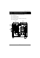
GA-8EGXRP Series Motherboard GA-8EGXRP Series Motherboard Layout COM 1 USB 2 COM 2 CMOS_CLR1 RJ1 RJ2 VGA 1 82550PM BIOS LPT ATX 2 CPU_FAN1 CPU SYS_FAN 2 SYS_FAN1 SYS_FAN 3 SCSI_EN1 Adaptec 7899W SCSI ATX 1 LAN2_EN1 VGA_EN1 ATI Range 82540EM XL GA-8EGXRP 64PCI 2 LAN1_EN1 64PCI 1 CMIC-SL CASEOPEN *SCSI 2 CLK_JP1 SYS_FAN4 SYS_FAN5 TERM_EN2 DIMM 1 DIMM 2 DIMM 3 DIMM 4 PCI 1 WRITE_P1 64PCI 4 WOL1 WOM1 64PCI 3 CSB6 TERM_EN1 IDE 1 IDE 2 FDD1 F_Panel1 PCI 2 Battery *SCSI 1 L MS_KB U
Hardw are Installation Process Chapter 2 Hardware Installation Process To set up your computer, you must complete the following setups: Step 1- Install the CPU Step 2- Install memory modules Step 3- Install expansion cards Step 4- Connect ribbon cables, cabinet wires, and power supply Step 5- Setup BIOS software Step 3 Step 4 Step 5 Step 4 Step 4 Step 1 Step 4 Step 2 9
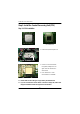
GA-8EGXRP Series Motherboard Step 1: Install the Central Processing Unit (CPU) Step 1-1: CPU Installation Pin1 indicator CPU Top View CPU Bottom View 1. Pull the lever out, than lift up the Lever. Socket Actuation Lever 2. Locate Pin 1 in the socket and look for a (golden) cut edge on the CPU upper corner. Then insert the CPU into the socket. Pin1 indicator 3. Press down the CPU socket lever and finish CPU installation. M Please make sure the CPU type is supported by the motherboard.
Hardw are Installation Process Step 1-2: CPU Heat Sink Installation 1. Use qualified fan approved by Intel. 2. Heat Sink 3. First step of assembling. 4. Completive picture for first step. 5. Second step of assembling. 6. Completive picture for second step.
GA-8EGXRP Series Motherboard 7. Fan assembly. 8. Hook one end of the cooler bracket to the CPU socket first. M You should apply the thermal paste to provide better heat conduction between your CPU and heatsink. M Make sure the CPU fan power cable is plugged in to the CPU fan connector, this completes the installation. M Please refer to CPU heat sink user’s manual for more detail installation procedure.
Hardw are Installation Process Step 2: Install memory modules The motherboard has 4 dual inline memory module (DIMM) sockets. The BIOS will automatically detects memory type and size. To install the memory module, just push it vertically into the DIMM Slot. The DIMM module can only fit in one direction due to the notch. Memory size can vary between sockets. Registered DDR 1. The DIMM slot has a notch, so the DIMM memory module can only fit in one direction. 2.
GA-8EGXRP Series Motherboard Step 3: Install expansion cards 1. Read the related expansion card’s instruction document before install the expansion card into the computer. 2. Remove your computer’s chassis cover, screws and slot bracket from the computer. 3. Press the expansion card firmly into expansion slot in motherboard. 4. Be sure the metal contacts on the card are indeed seated in the slot. 5. Replace the screw to secure the slot bracket of the expansion card. 6.
Hardw are Installation Process Step 4: Connect ribbon cables, cabinet wires, and power supply Step 4-1: I/O Back Panel Introduction w u v x y u PS/2 Keyboard and PS/2 Mouse Connector PS/2 Mouse Connector (6 pin Female) ØThis connector supports standard PS/2 keyboard and PS/2 mouse. PS/2 Keyboard Connector (6 pin Female) v USB Connector USB 0 USB 1 ØBefore you connect your device(s) into USB connector(s), please make sure your device(s) such as USB keyboard, mouse, scanner, zip, speaker..etc.
GA-8EGXRP Series Motherboard w Parallel Port / Serial Port / VGA Port (LPT/COMA/VGA) Parallel Port (25 pin Female) COMA Serial Port (9 pin Male) ØThis connector supports 1 standard COM port ,1 Parallel port and 1 VGA port. Device like printercan be connected to Parallel port ; mouse and modem etc can be connected to Serial ports.
Hardw are Installation Process Step 4-2: Connectors Introduction R T P H G A Q F B I J K E C D L N O S M L A) ATX1 K ) System FAN 3 B) ATX2 L ) System FAN 4 C) IDE1 M ) System FAN 5 D) IDE2 N ) SCSI 1* E) FDD1 O ) SCSI 2* F) F_PANEL1 P ) CPU FAN1 G) USB2 Q ) WOL1 H) COM2 R ) WOM1 I) System FAN 1 S ) CASEOPEN J ) System FAN 2 T ) BT Note: the * indicates the feature is available for GA-8EGXRP and GA-8EGXRP-E models only 17
GA-8EGXRP Series Motherboard A) ATX1 (2x10 Pin ATX Power ) +12V 5V SB (Stand by +5V) Power Good GND VCC GND VCC GND 3.3V 3.3V VCC VCC -5V GND GND GND PS-ON(SoftOn/Off) GND -12V 3.3V Ø AC power cord should only be connected to your power supply unit after ATX power cable and other related devices are firmly connected to the mainboard. B) ATX2 (+12V Power Connector) +12V +12V ØThis connector (ATX +12V) is used only for CPU Core Voltage.
Hardw are Installation Process I / J / K / L / M) System FAN 1/2/3/4/5 Connectors J34 J31 Sense +12V/Control GND 1 1 GND Sense +12V/Control H) COM 2 Connector NDTRBNSINB NDSRB- Q) Wake On LAN Connector 1 NCTSBNC 1 NDCDBNSOUTB GND +5V SB GND Signal NRIBNRTSB- N / O) *SCSI1/*SCSI2 Connector R) Wake On Ring Connector 1 GND Signal L Note: the * indicates the feature is available for GA-8EGXRP and GA-8EGXRP-E models only 19
GA-8EGXRP Series Motherboard C / D) IDE 1/ IDE 2/ [IDE1 / IDE2 / Connectors(Primary/Secondary)] 1 IDE2 1 IDE1 E) FDD1 (Floppy Connector) 1 Floppy G) USB2 USB D2+ GND GND USB D2Power Power USB D3- GND ØBe careful with the polarity of the front panel USB connector. Check the pin assignment while you connect the front panel USB cable. Please contact your nearest dealer for optional front panel USB cable.
Hardw are Installation Process S) CASE OPEN ØPlease note that uder normal circumstance, the CASEOPEN connector is set at closed status. When it is at open status (for example, the chassis cover is opened) system will alarm warning beeping. We recommend user to use the Normal-Close switch. 1 Signal GND T) BT1 (Battery) Li-Battery 3V CAUTION + CR2032 v Danger of explosion if battery is incorrectly replaced. v Replace only with the same or equivalent type recommended by the manufacturer.
GA-8EGXRP Series Motherboard F) F_PANEL1 (2x12 Pins connector) 1 PD+ KEY PDHD+ HDPW+ PWRS+ RSGN+ GNSMI FF SK+ NC NC SKLD1+ LD1SDA SCL COP LD2+ LD230 1) PD+ (Power LED) 2) FF (No Connect) 3) KEY 4) SK+ (Speaker) 5) PD- (Power LED) 6) NC (No Connect) 7) HD+ (HDD LED) 8) NC (No Connect) 9) HD- (HDD LED) 10) SK- (Speaker) 11) PW+ (Power Button) 12) LD1+ (LAN1 LED Active) 13) PW- (Power Button) 14) LD1- (LAN1 LED Active) 15) RS+ (Reset Button) 16) I 2C_SDA 17) RS- (Reset Button) 18) I 2C_SCL
Jumper Setting Step 4-3: Jumper Setting Introduction 9 2 3 8 7 6 1) 2) 3) 4) 5) G 4 5 1 CLK_JP1 LAN1_EN1 LAN2_EN1 SCSI_EN1 * TERM_EN2 6) 7) 8) 9) TERM_EN1 VGA_EN1 WRITE_P1 CMOS_CLR1 Please note that the highlight white mark on the motherboard is presented as Pin 1 L Note: the * indicates the feature is available for GA-8EGXRP and GA-8EGXRP-E models only 23
GA-8EGXRP Series Motherboard 1) CLK_JP1 1 1-2 close: Auto (Default) 1 2-3 close: CPU Speed at 533MHz 1 None: CPU Speed at 400MHz G Please note that the the highlight white mark is presented as Pin 1.
Jumper Setting 4) SCSI_EN1 (SCSI Function) * 1 1-2 close: SCSI Enabled (Default) 1 2-3 close: SCSI Disabled Note: the * indicates the feature is av ailable for GA-8EGXRP and GA-8EGXRPE models only 5) TERM_EN2 (SCSI On-Board Terminator Function) 1 1-2 close: SCSI Terminator Enabled (Default) 1 2-3 close: SCSI Terminator Disabled 6) TERM_EN1 (SCSI On-Board Terminator Function) 1 1 25 1-2 close: SCSI Terminator Enabled (Default) 2-3 close: SCSI Terminator Disabled
GA-8EGXRP Series Motherboard 7) VGA_EN1 (VGA Function) 1 1-2 close: VGA Enabled (Default) 1 2-3 close: VGA Disabled 8) WRITE_P1 (Write Protect Function) 1 1-2 close: BIOS Write Protect Enables 1 2-3 close: Writer Protect Disabled (Default) 9) CMOS_CLR1 (Clear CMOS Function) 1 1-2 close: Clear CMOS 1 2-3 close: Normal (Default) Ø Please note, You may clear the CMOS data to its default values by this jumper 26
GA-8EGXRP Series Motherboard Chapter 3 BIOS Setup BIOS Setup is an overview of the BIOS Setup Program. The program that allows users to modify the basic system configuration. This type of information is stored in battery-backed CMOS RAM so that it retains the Setup information when the power is turned off. ENTERING SETUP Power ON the computer and press immediately will allow you to enter Setup.
BIOS Setup GETTING HELP Main Menu The on-line description of the highlighted setup function is displayed at the bottom of the screen. Status Page Setup Menu / Option Page Setup Menu Press F1 to pop up a small help window that describes the appropriate keys to use and the possible selections for the highlighted item. To exit the Help Window press . l Main This setup page includes all the items in standard compatible BIOS.
GA-8EGXRP Series Motherboard Main (For example: BIOS Ver. : F1) Once you enter AMI BIOS CMOS Setup Utility, the Main Menu (Figure 1) will appear on the screen. Use arrow keys to select among the items and press to accept or enter the sub-menu. AMI EASY Setup Utility Main Adv anced Security Boot Sy stem Date: Aug 14 2002 Sy stem Time: 00:13:12 Floppy Driv e A: 1.
BIOS Setup C Floppy Drive A/B This category identifies the type of floppy disk drive A or drive B that have been installed in the computer. 8None No floppy driv e installed 81.2MB, 3.5 in. 3.5 inch AT-ty pe high-density driv e; 1.2M by te capacity 8720K, 3.5 in. 3.5 inch double-sided driv e; 720K by te capacity 81.44M, 3.5 in. 3.5 inch double-sided driv e; 1.44M by te capacity . 82.88M, 3.5 in. 3.5 inch double-sided driv e; 2.88M by te capacity .
GA-8EGXRP Series Motherboard 8Fast Programmed I/O Mode This field only show s the information of Fast Programmed I/O Mode. 832 Bit Transfer Mode Enables 32 bit access to max imize the hard disk data transfer rate. Option: On (Default Value); Off If a hard disk has not been installed select NONE and press . C System Information This category displays the system information on CPU and Memory.
BIOS Setup Advanced AMI EASY Setup Utility Main Adv anced Security Boot Ex it [Setup Help] } Adv anced Configuration } Chipset Configuration } Pow er Management Configuration } Plug & Play Configuration }Peripheral Configuration }Hardw are Monitor Configuration F1: Help Esc: Ex it hi: Select Item fg: Select Menu + -: Change Values F5: Setup Defaults Enter: Select4Sub-Menu F10: Sav e&Ex it Figure 2: Adv anced G About This Section: Advanced This section “Advanced” is divided into six sub-menus.
GA-8EGXRP Series Motherboard Advanced Configuration AMI EASY Setup Utility Main Adv anced Security Boot Ex it Adv anced Configuration [Setup Help] Show Full Screen Logo Enabled S.M.A.R.T for Hard Disk Disabled MPS Version for O.S 1.
BIOS Setup C Advanced Configuration This category allow user to configure advanced functions . } Show Full Screen Logo 8Enabled Enable Show Full Screen Logo function.(Default Value) 8Disabled Disable this function. } S.M.A.R.T for Hard Disk This filed shows if the device in the specific IDE channel supports S.M.A.R.T. S.M.A.R.Tstands for Self-Monitoring Analysis and Reporting Technology. 8Enabled Set this option “Enable” to permit BIOS to use S.M.A.R.T. 8Disabled Disable S.M.A.R.T function.
GA-8EGXRP Series Motherboard Chipset Configuration AMI EASY Setup Utility Main Adv anced Security Boot Ex it Chipset Configuration [Setup Help] Memroy Scrubbing F1: Help Esc: Ex it Enabled hi: Select Item fg: Select Menu + -: Change Values F5: Setup Defaults Enter: Select4Sub-Menu F10: Sav e&Ex it Figure 2-2: Chipset Configuration C Chipset Configuration } Memory Scrubbing 8Enabled Enable this option to write back the ECC corrected memory data to the DRAM.
BIOS Setup Power Management Configuration AMI EASY Setup Utility Main Adv anced Security Boot Ex it Pow er Management Configuration [Setup Help] Soft-off by Pow er Button Instant-off Sleep Button Enabled Wake Up On Ring 1.
GA-8EGXRP Series Motherboard } Wake Up Ring Sy stem is w aken up w hen Moderm-Ring is on. 8Enabled Enable Wake Up Ring. (Default Value) 8Disabled Disable this function. } System After AC Back System power state when AC cord is re-plugged. 8Pre-State Set system power to the last state when AC power is removed. 8OFF Do not power on system when AC power is back.
BIOS Setup Plug and Play Configuration AMI EASY Setup Utility Main Adv anced Security Boot Ex it Plug and Play Configuration [Setup Help] PCI Slot 1/5 IRQ Priority Auto PCI Slot 2/6 IRQ Priority Auto PCI Slot 3 IRQ Priority Auto PCI Slot 4 IRQ Priority IRQ 3 Auto PCI/PnP IRQ 4 PCI/PnP IRQ 5 PCI/PnP IRQ 7 PCI/PnP IRQ 9 PCI/PnP IRQ 10 PCI/PnP IRQ 11 PCI/PnP IRQ 14 PCI/PnP F1: Help Esc: Ex it hi: Select Item fg: Select Menu + -: Change Values F5: Setup Defaults Enter: Select4Sub
GA-8EGXRP Series Motherboard C Plug & Play Configuration This option describes the configuration of PCI bus system, or Personal Conputer Interconnect, is a system which allows I/O devices to operate at a speeds nearing the speed the CPU itself uses when communicating with its own special components. This section covers some technical items and it is stongly recommended that only experienced users should make any changes to the default settings. } PCI Slot 1/5 IRQ Priority Select PCI Slot 1/5 IRQ Priority.
BIOS Setup Peripheral Configuration AMI EASY Setup Utility Main Adv anced Security Boot Ex it Peripheral Configuration [Setup Help] OnBoard IDE Both OnBoard FDC Enabled OnBoard Serial Port A 3F8/COM1 OnBoard Serial Port B 2F8/COM2 OnBoard Parallel Port 378 Parallel Port Mode ECP Parallel Port IRQ 7 Parallel Port DMA 3 USB Function Enabled USB Legacy Disabled Port 64/60 Emulation Disabled F1: Help Esc: Ex it hi: Select Item fg: Select Menu + -: Change Values F5: Setup Defaults
GA-8EGXRP Series Motherboard } OnBoard Serial Port A This option specifies the base I/O port address of serial prot A. 83F8/COM1 Enable onboard serial port A and set I/O address to 3F8/COM1. (Default value) 82F8/COM2 Enable onboard serial port A and set I/O address to 2F8/COM2. 83E8/COM3 Enable onboard serial port A and set I/O address to 3E8/COM3. 82E8/COM4 Enable onboard serial port A and set I/O address to 2E8/COM4.
BIOS Setup 8ECP The parallel port can be used with devices that adhere to the extended Capabilities Port specifications. ECP uses the DMA protocol to achieve data transfer rate up to 2.5Mbit/s. ECP provides the symmetric bi-directional communication. (Default value) } Parallel Port IRQ This option is to select Parallel Port IRQ Option: 7 (Default Value) , 5 } Parallel Port DMA This option iallows user to select Parallel Port DMA.
GA-8EGXRP Series Motherboard Hardware Monitor Configuration AMI EASY Setup Utility Main Adv anced Security Boot Ex it Hardw are Monitor Configuration [Setup Help] CPU Temperature +39°C/+102°F Sy stem Temperature +39°C/+102°F CPU_FAN Speed RPM SYS_FAN1 Speed SYS_FAN2 Speed RPM RPM SYS_FAN3 Speed RPM SYS_FAN4 Speed RPM VCC_P 1.952V VCC 2.5 0.000V VCC 3 0.000V VCC 5 0.000V VCC 12 0.000V VBAT 0.000V 5VSB 0.000V Hardw are Monitor Alarm Disabled SYS_TEM.
BIOS Setup C Hardware Monitor Confi guration This section prov ides the sy stem hardw are health information to user for reference. } CPU Temperature This field only displlay s the current CPU temperature. } System Temperature This field only displlay s the current sy stem temperature. } CPU FAN Speed This field indicates the RPM (Ratio Per Minute) of current CPU speed. } SYS FAN 1 / 2 / 3 /4 Speed This field indicates the RPM (Ratio Per Minute) of Sy stem Fan 1/2/3/4 speed. } VCC_P / VCC 2.
GA-8EGXRP Series Motherboard } CPU_FAN1/2/3/4 / SYS_FAN1/2/3/4 Buzzer Alarm When this function is enabled, sy stem w ill alarm w hen CPU FAN1/2/3/4 stop. 8Enabled Enable CPU FAN1/2/3/4 buzzer alarm. 8Disabled Disable this function. } VCC_P Buzzer Alarm Enable this function is protecting the sy stem v oltage is under the set v alue. Sy stem w ill alarm w hen the v oltage is ov er the set v alue. 8Enabled Enable VCC_P buzzer alarm. 8Disabled Disable this function.
BIOS Setup Security AMI EASY Setup Utility Main Adv anced Security Boot Ex it No] [Setup Help] Set Superv isor Passw ord [Enter] Set User Passw ord [Enter] Passw ord Check Setup F1: Help Esc: Ex it hi: Select Item fg: Select Menu + -: Change Values F5: Setup Defaults Enter: Select4Sub-Menu F10: Sav e&Ex it Figure 3: Security G About This Section: Security In this section, user can set either supervisor or user passwords, or both for different level of password securities.
GA-8EGXRP Series Motherboard CSet Supervis or Password You can install and change this options for the setup menus. Type the password up to 6 characters in lengh and press . The password typed now will clear any prev iously entered password from the CMOS memory. You w ill be asked to confirm the entered password. Type the password again and press . You may also press to abort the selection and not enter a specified password or press key to disable this option.
BIOS Setup Boot AMI EASY Setup Utility Main Adv anced Security Boot Ex it [Setup Help] Boot Dev ice Priority Floppy : 1.
GA-8EGXRP Series Motherboard The Choice for 1st Boot Device: Removable Device (Default Value) , ATAPI CDROM, Hard Disk, Disabled. The Choice for 2nd Boot Device: Removable Device , ATAPI CDROM (Default Value) , Hard Disk, Disabled. The Choice for 3rd Boot Device: Removable Device , ATAPI CDROM, Hard Disk (Default Value), Disabled. } OnBoard 82540 LAN Boot ROM 8Enabled Enable OnBoard 82540 LAN Boot ROM. (Default Value) 8Disabled Disable this function.
BIOS Setup Exit AMI EASY Setup Utility Main Adv anced Security Boot Ex it [Setup Help] Ex it Sav ing Changes Enter Ex it Discarding Changes Enter Load Default Settings Enter Load Original Values Enter F1: Help Esc: Ex it hi: Select Item fg: Select Menu + -: Change Values F5: Setup Defaults Enter: Select4Sub-Menu F10: Sav e&Ex it Figure 5: Ex it G About This Section: Security Once you have changed all of the set values in the BIOS setup, you should save your chnages and exit BIOS setup prog
GA-8EGXRP Series Motherboard CExit Saving Changes This option allows user to exit system setup with saving the changes. Press on this item to ask for the following confirmation message: Pressing ‘Y’to store all the present setting values tha user made in this time into CMOS. Therefore, whenyou boot up y our computer next time, the BIOS will re-configure your system according data in CMOS.
Technical Reference Revision History Chapter 4 Technical Reference Block Diagram 51
GA-8EGXRP Series Motherboard Revision History Chapter 5 Appendix Appendix A: Intel 82540EM 82550PM Network Driver Installation (For example: Driver CD Ver. : 1.0) Insert the driver CD-title that came with your motherboard into your CD-ROM driver, the driver CD-title will auto start and show a series of Setup Wizard dialog boxes. If not, please double click the CD-ROM device icon in "My computer", and execute the setup.exe. 2.Intel(R) PRO Intelligent Installer welcome window appears.
Appendix 5. Ready to install the program. Click "Install" to begin the installation. 6. Starting installation (5) (6) 7. Wizard completed. Click "Finish". 8. Installation Result. Click "OK" to close the window.
GA-8EGXRP Series Motherboard Appendix B: ATI Rage XL VGA Driver Installation Insert the driver CD-title that came with your motherboard into your CD-ROM driver, the driver CD-title will auto start and show the installation guide. If not, please double click the CD-ROM device icon in "My computer", and execute the setup.exe. 2.Click "Next". 1.Click "ATI Rage XL VGA Driver" item. (1) (2) 4. Select “Yes, I want to restart my computer” item and click "Finish" to restart computer. 3.
Appendix Appendix C: Adaptec SCSI Driver Installation Insert the driver CD-title that came with your motherboard into your CD-ROM driver, the driver CD-title will auto start and show the installation guide. If not, please double click the CD-ROM device icon in "My computer", and execute the setup.exe. 2. A READ ME file pops up will guide you the installation procedures depends on the different operating system. 1. Click "Adaptec PCI SCSI Driver" item.
GA-8EGXRP Series Motherboard Appendix D: Utilities Installation Insert the driver CD-title that came with your motherboard into your CD-ROM driver, the driver CD-title will auto start and show the installation guide. If not, please double click the CD-ROM device icon in "My computer", and execute the setup.exe. The Utilities item contains the utility of DirectX 8.1, Adabe Acrobate Reader V.5.0, and Norton Internet Security 2002 1. Click "Utilities" item. 2.
GA-8EGXRP Series Motherboard Appendix G: Acronyms Acronyms ACPI APM AGP AMR ACR BBS BIOS CPU CMOS CRIMM CNR DMA DMI DIMM DRM DRAM DDR ECP ESCD ECC EMC EPP ESD FDD FSB HDD IDE IRQ I/O IOAPIC ISA Meaning Advanced Configuration and Power Interface Advanced Power Management Accelerated Graphics Port Audio Modem Riser Advanced Communications Riser BIOS Boot Specification Basic Input / Output System Central Processing Unit Complementary Metal Oxide Semiconductor Continuity RIMM Communication and Networking Rise
GA-8EGXRP Series Motherboard Acronyms LAN LBA LED MHz MIDI MTH MPT NIC OS OEM PAC POST PCI RIMM SCI SECC SRAM SMP SMI USB VID ZCR Meaning Local Area Network Logical Block Addressing Light Emitting Diode Megahertz Musical Instrument Digital Interface Memory Translator Hub Memory Protocol Translator Network Interface Card Operating System Original Equipment Manufacturer PCI A.G.P.
Appendix & Technical Support/RMA Sheet Customer/Country: Contact Person: Company: E-mail Add. : Model name/Lot Number: BIOS version: O.S./A.S.: Hardware Configuration CPU Memory Brand Video Card Audio Card HDD CD-ROM / DVD-ROM Modem Network AMR / CNR Keyboard Mouse Power supply Other Device Mfs. Phone No.