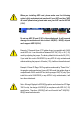
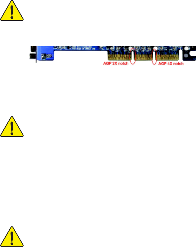
When you installing AGP card, please make sure the following notice is fully understood and practiced. If your AGP card has "AGP 4X notch"(show below), please make sure your AGP card is AGP 4X (1.5V). Do not use AGP 2X card (3.3V) in this motherboard. It will burn and damage the motherboard due to Intel® 845(E/G) / 850(E) chipset can't support AGP 2X(3.3V). Example 1: Diamond Vipper V770 golden finger is compatible with 2X/4X mode AGP slot. It can be switched between AGP 2X(3.3V) or 4X (1.
The author assumes no responsibility for any errors or omissions that may appear in this document nor does the author make a commitment to update the information contained herein. Third-party brands and names are the property of their respective owners. Please do not remove any labels on motherboard, this may void the warranty of this motherboard. Due to rapid change in technology, some of the specifications might be out of date before publication of this booklet.
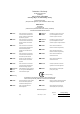
Declaration of Conformity We, Manufacturer/Importer (full address) .. G.B.T.
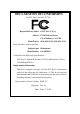
DECLARATION OF CONFORMITY Per FCC Part 2 Section 2.1077(a) Responsible Party Name: G.B.T. INC. (U.S.A.) Address: 17358 Railroad Street City of Industry, CA 91748 Phone/FaxNo: (818) 854-9338/ (818) 854-9339 hereby declares that the product Product Name: Motherboard ModelNumber: GA-8IR2003 Conforms to the following specifications: FCC Part 15, Subpart B, Section 15.107(a) and Section 15.109(a), Class B Digital Device Supplementary Information: This device complies with part 15 of the FCC Rules.
GA-8IR2003 P4 Titan DDR Motherboard USER'S MANUAL Pentium® 4 Processor Motherboard Rev.
English Table of Content Item Checklist ......................................................................................... 4 WARNING! ............................................................................................... 4 Chapter 1 Introduction ............................................................................ 5 Features Summary ...................................................................................... 5 GA-8IR2003 Motherboard Layout ..................................
Load Fail-Safe Defaults ............................................................................. 48 Load Optimized Defaults ........................................................................... 49 Set Supervisor/User Password .................................................................. 50 Save & Exit Setup ....................................................................................... 51 Exit Without Saving ............................................................................
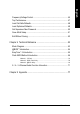
English Item Checklist The GA-8IR2003 motherboard 2 Port USB Cable x 1 IDE cable x 1 / Floppy cable x 1 4 Port USB Cable x 1 SPDIF KIT x 1 (SPD-KIT) CD for motherboard driver & utility I/O Shield IEEE 1394 Cable x 1 Audio Combo Kit x 1 Quick PC Installation Guide Motherboard Settings Label GA-8IR2003 user's manual RAID Manual WARNING! Computer motherboards and expansion cards contain very delicate Integrated Circuit (IC) chips.
Features Summary Form Factor CPU Chipset Memory I/O Control Slots On-Board IDE y y y y y y y y y y y y y y y y y y y On-Board Peripherals y Hardware Monitor y y y y y y y y y 19.6cm x 29.5cm ATX size form factor, 4 layers PCB Socket 478 for Intel® Micro FC-PGA2 Pentium® 4 processor Support Intel® Pentium® 4 (Northwood, 0.
English On-Board Sound PS/2 Connector BIOS Additional Features Jumper less Overclocking y y y y y y y y y y y y y y y y y y Realtek ALC650 CODEC Line Out / 2 front speaker Line In / 2 rear speaker(by s/w switch) Mic In / center & subwoofer(by s/w switch) SPDIF In / Out CD In / AUX In / Game port PS/2 Keyboard interface and PS/2 Mouse interface Licensed AWARD BIOS, 2M bit FWH Supports Q-Flash PS/2 Keyboard password power on PS/2 Mouse power on STR(Suspend-To-RAM) AC Recovery USB KB/Mouse wake up from S3
English GA-8IR2003 Motherboard Layout KB_MS LPT COMA ATX USB GA-8IR2003 GAME ATX_12V CPU_FAN CODEC 2X_DET BATTERY PCI1 PCI2 SYS _FAN SUR_CEN PCI3 DDR3 CD_IN DDR2 Intel 845 AGP DDR1 MIC_IN LINE_OUT LINE_IN F_AUDIO FDD COMB SOCKET478 CLR_PWD ICH2 CI P4 Titan PCI4 IDE2 PCI5 ITE8712 PWR_LED AUX_IN SPDIF_IO IDE1 BIOS F_USB1 -7- F_PANEL Hardware Installation Process
English Chapter 2 Hardware Installation Process To set up your computer, you must complete the following steps: Step 1- Install the Central Processing Unit (CPU) Step 2- Install memory modules Step 3- Install expansion cards Step 4- Connect ribbon cables, cabinet wires, and power supply Step 5- Setup BIOS software Step 6- Install supporting software tools Step 4 Step 1 Step 2 Step 4 Step 4 Step 1 Step 3 Step 4 GA-8IR2003 Motherboard -8-
Step 1-1: CPU Installation Socket Actuation Lever Angling the rod to 650 1. Angling the rod to 65-degree maybe feel a kind of tight , and then continue pull the rod to 2. Pull the rod to the 90-degree directly . 90-degree when a noise "cough" made. Pin1 indicator Pin1 indicator 3. CPU Top View 4. Locate Pin 1 in the socket and look for a (golden) cut edge on the CPU upper corner. Then insert the CPU into the socket. Please make sure the CPU type is supported by the motherboard.
English Step 1-2: CPU Heat Sink Installation 2. Hook the other end of the cooler 1. Hook one end of the cooler bracket bracket to the CPU socket. to the CPU socket first. Please use Intel approved cooling fan. We recommend you to apply the thermal tape to provide better heat conduction between your CPU and heatsink. (The CPU cooling fan might stick to the CPU due to the hardening of the thermal paste.
The motherboard has 3 dual inline memory module (DIMM) sockets, but it can only support a maximum of 4 banks of DDR memory. DDR slot 1 uses 2 banks, DDR slot 2 & 3 share the remaining 2 banks. Please refer to the following tables for possible memory configurations supported. The BIOS will automatically detects memory type and size. To install the memory module, just push it vertically into the DIMM socket. The DIMM module can only fit in one direction due to the notch. Memory size can vary between sockets.
English DDR 1. The DIMM socket has a notch, so the DIMM memory module can only fit in one direction. 2. Insert the DIMM memory module vertically into the DIMM socket. Then push it down. 3. Close the plastic clip at both edges of the DIMM sockets to lock the DIMM module. Reverse the installation steps when you wish to remove the DIMM module.
1. Read the related expansion card's instruction document before install the expansion card into the computer. 2. Remove your computer's chassis cover, screws and slot bracket from the computer. 3. Press the expansion card firmly into expansion slot in motherboard. 4. Be sure the metal contacts on the card are indeed seated in the slot. 5. Replace the screw to secure the slot bracket of the expansion card. 6. Replace your computer's chassis cover. 7.
English Step 4: Connect ribbon cables, cabinet wires and power supply Step 4-1: I/O Back Panel Introduction Z [ X Y \ X PS/2 Keyboard and PS/2 Mouse Connector PS/2 Mouse Connector (6 pin Female) This connector supports standard PS/2 keyboard and PS/2 mouse. PS/2 Keyboard Connector (6 pin Female) Y USB Connector Before you connect your device(s) into USB connector(s), please make sure your device(s) such as USB keyboard,mouse, scanner, zip, USB 0 USB 1 speaker...etc. Have a standard USB interface.
Parallel Port (25 pin Female) This connector supports 2 standard COM ports and 1 Parallel port. Device like printer can be connected to Parallel port; mouse and modem etc. can be connected to Serial ports. COMA COMB Serial Port (9 pin Male) This connector supports joystick, MIDI keyboard and other relate audio devices.
English Step 4-2: Connectors Introduction 2 1 5 10 3 9 12 18 11 4 17 16 6 8 13 14 1) 2) 3) 4) 5) 6) 7) 8) 9) ATX_12V ATX CPU_FAN SYS_FAN FDD IDE1 / IDE2 F_PANEL PWR_LED 2X_DET GA-8IR2003 Motherboard 15 10) 11) 12) 13) 14) 15) 16) 17) 18) - 16 - 7 F_AUDIO SUR_CEN CD_IN AUX_IN SPDIF_IO F_USB1 CI CLR_PWD BATTERY
English 1) ATX_12V (+12V Power Connector) This connector (ATX_12V) supplies the CPU operation voltage (Vcore). If this "ATX_12V connector" is not connected, system cannot boot. Pin No. 2 4 1 3 Definition 1 2 GND GND 3 4 +12V +12V 2) ATX (ATX Power) AC power cord should only be connected to your power supply unit after ATX power cable and other related devices are firmly connected to the mainboard. Pin No. 10 1 - 17 - 20 11 Definition 1 2 3.3V 3.
English 3) CPU_FAN (CPU Fan Connector) Please note, a proper installation of the CPU cooler is essential to prevent the CPU from running under abnormal condition or damaged by overheating. The CPU fan connector supports Max. current up to 600 mA. Pin No. 1 Definition 1 2 GND +12V 3 Sense 4) SYS_FAN (System Fan Connector) This connector allows you to link with the cooling fan on the system case to lower the system temperature. 1 GA-8IR2003 Motherboard - 18 - Pin No.
Please connect the floppy drive ribbon cables to FDD. It supports 360K, 1.2M, 720K, 1.44M and 2.88M bytes floppy disk types. The red stripe of the ribbon cable must be the same side with the Pin1. 34 33 2 1 6) IDE1 / IDE2 (IDE1 / IDE2 Connector) Important Notice: Please connect first hard disk to IDE1 and connect CD-ROM to IDE2. The red stripe of the ribbon cable must be the same side with the Pin1.
Please connect the power LED, PC speaker, reset switch and power switch etc of your chassisfront panel to the F_PANEL connector according to the pin assignment above.
PWR_LED is connect with the system power indicator to indicate whether the system is on/off. It will blink when the system enters suspend mode. If you use dual color LED, power LED will turn to another color. 1 Pin No. 1 2 3 Definition MPD+ MPDMPD- 9) 2X_DET When an AGP 2X (3.3V) card is installed the AGP_LED will light up, indicating a non-supported graphics card is inserted. Informing users that system might not boot up normally due to AGP 2X (3.3V) is not supported by the chipset.
English 10) F_AUDIO (Front Audio Connector) If you want to use Front Audio connector, you must remove 5-6, 9-10 Jumper. In order to utilize the front audio header, your chassis must have front audio connector. Also please make sure the pin assigment on the cable is the same as the pin assigment on the MB header. To find out if the chassis you are buying support front audio connector, please contact your dealer.
English 12) CD_IN (CD In Connector) Connect CD-ROM or DVD-ROM audio out to the connector. 1 Pin No. Definition 1 2 AUX-L GND 3 4 GND AUX-R 13) AUX_IN (AUX In Connector) Connect other device (such as PCI TV Tunner audio out) to the connector. 1 - 23 - Pin No.
English 14) SPDIF_IO (SPDIF In / Out) The SPDIF output is capable of providing digital audio to external speakers or compressed AC3 data to an external Dolby Digital Decoder. Use this feature only when your stereo system has digital input function. Use SPDIF IN feature only when your device has digital output function. 5 1 6 2 Pin No. Definition 1 2 VCC No Pin 3 4 SPDIF SPDIFI 5 6 GND GND 15) F_USB1 (Front USB Connector, Yellow) Be careful with the polarity of the front USB connector.
This 2-pin connector allows your system to enable or disable the "Case Open" item in BIOS, if the system case begin remove. 1 Pin No. Definition 1 2 Signal GND 17) CLR_PWD When Jumper is set to "open" and system is restarted, the password that is set will be cleared. On the contrary when Jumper is set to "close", the current status remains.
English 18) BATTERY + CAUTION Danger of explosion if battery is incorrectly replaced. Replace only with the same or equivalent type recommended by the manufacturer. Dispose of used batteries according to the manufacturer's instructions. If you want to erase CMOS... 1. Turn OFF the computer and unplug the power cord. 2. Remove the battery, wait for 30 second. 3. Re-install the battery. 4. Plug the power cord and turn ON the computer.
BIOS Setup is an overview of the BIOS Setup Program. The program that allows users to modify the basic system configuration. This type of information is stored in battery-backed CMOS RAM so that it retains the Setup information when the power is turned off. ENTERING SETUP Powering ON the computer and pressing immediately will allow you to enter Setup. If you require more advanced BIOS settings, please go to "Advanced BIOS" setting menu.
English GETTING HELP Main Menu The on-line description of the highlighted setup function is displayed at the bottom of the screen. Status Page Setup Menu / Option Page Setup Menu Press F1 to pop up a small help window that describes the appropriate keys to use and the possible selections for the highlighted item. To exit the Help Window press . The Main Menu (For example: BIOS Ver. : E1) Once you enter Award BIOS CMOS Setup Utility, the Main Menu (Figure 1) will appear on the screen.
Integrated Peripherals English z This setup page includes all onboard peripherals. z Power Management Setup This setup page includes all the items of Green function features. z PnP/PCI Configurations This setup page includes all the configurations of PCI & PnP ISA resources. z PC Health Status This setup page is the System auto detect Temperature, voltage, fan, speed. z Frequency/Voltage Control This setup page is control CPU’s clock and frequency ratio.
English Standard CMOS Features CMOS Setup Utility-Copyright (C) 1984-2003 Award Software Standard CMOS Features Date (mm:dd:yy) Thu, Jan 9 2003 Time (hh:mm:ss) 22:31:24 Item Help Menu Level Change the day, month, IDE Primary Master [None] IDE Primary Slave [None] year IDE Secondary Master [None] IDE Secondary Slave [None] Sun. to Sat. Drive A [1.44M, 3.5"] Drive B [None] Jan. to Dec.
The times format in . The time is calculated base on the 24-hour militarytime clock. For example, 1 p.m. is 13:00:00. & IDE Primary Master, Slave / IDE Secondary Master, Slave The category identifies the types of hard disk from drive C to F that has been installed in the computer. There are two types: auto type, and manual type. Manual type is user-definable; Auto type which will automatically detect HDD type.
English & Floppy 3 Mode Support (for Japan Area) Disabled Normal Floppy Drive. (Default value) Drive A Drive A is 3 mode Floppy Drive. Drive B Drive B is 3 mode Floppy Drive. Both Drive A & B are 3 mode Floppy Drives. & Halt on The category determines whether the computer will stop if an error is detected during power up. NO Errors The system boot will not stop for any error that may be detected and you will be prompted.
English Advanced BIOS Features CMOS Setup Utility-Copyright (C) 1984-2003 Award Software Advanced BIOS Features First Boot Device [Floppy] Item Help Second Boot Device [HDD-0] Menu Level Third Boot Device [CDROM] Select Boot Device Boot Up Floppy Seek [Disabled] priority Password Check [Setup] CPU Hyper-Threading # [Enabled] [Floppy] DRAM Data Integrity Mode [Non-ECC] Boot from floppy Init Display First [AGP] [LS120] Boot from LS120 [HDD-0] Boot from First HDD [HDD-1] Boot from second
English USB-CDROM Select your boot device priority by USB-CDROM. USB-HDD Select your boot device priority by USB-HDD. LAN Select your boot device priority by LAN. Disabled Select your boot device priority by Disabled. & Boot Up Floppy Seek During POST, BIOS will determine the floppy disk drive installed is 40 or 80 tracks. 360K type is 40 tracks 720K, 1.2M and 1.44M are all 80 tracks. Enabled BIOS searches for floppy disk drive to determine it is 40 or 80 tracks.
English Integrated Peripherals CMOS Setup Utility-Copyright (C) 1984-2003 Award Software Integrated Peripherals On-Chip Primary PCI IDE [Enabled] Item Help On-Chip Secondary PCI IDE [Enabled] Menu Level IDE1 Conductor Cable [Auto] [Auto] IDE2 Conductor Cable [Auto] Auto-detect IDE USB Controller [Enabled] cable type USB Keyboard Support [Disabled] USB Mouse Support [Disabled] [ATA66/100/133] AC97 Audio [Auto] Set Conductor cable Onboard Serial Port 1 [3F8/IRQ4] to ATA66/100/133(80
English & IDE1 Conductor Cable Auto Will be automatically detected by BIOS. (Default Value) ATA66/100 Set IDE1 Conductor Cable to ATA66/100 (Please make sure your IDE device and cable is compatible with ATA66/100). ATA33 Set IDE1 Conductor Cable to ATA33 (Please make sure your IDE device and cable is compatible with ATA33). & IDE2 Conductor Cable Auto Will be automatically detected by BIOS.
Auto BIOS will automatically setup the port 1 address. 3F8/IRQ4 Enable onboard Serial port 1 and address is 3F8. (Default value) 2F8/IRQ3 Enable onboard Serial port 1 and address is 2F8. 3E8/IRQ4 Enable onboard Serial port 1 and address is 3E8. 2E8/IRQ3 Enable onboard Serial port 1 and address is 2E8. Disabled Disable onboard Serial port 1. English & Onboard Serial Port 1 & Onboard Serial Port 2 Auto BIOS will automatically setup the port 2 address.
English &Game Port Address 201 Set Game Port Address to 201. (Default Value) 209 Set Game Port Address to 209. Disabled Disable this function. &Midi Port Address 290 Set Midi Port Address to 290. 300 Set Midi Port Address to 300. 330 Set Midi Port Address to 330.(Default Value) Disabled Disable this function. & Midi Port IRQ 5 Set Midi Port IRQ to 5. 10 Set Midi Port IRQ to 10.
English Power Management Setup CMOS Setup Utility-Copyright (C) 1984-2003 Award Software Power Management Setup ACPI Suspend Type [S1(POS)] Item Help Power LED in S1 state [Blinking] Menu Level Soft-Off by PWR-BTTN [Instant-Off] [S1] PME Event Wake Up [Enabled] Set suspend type to ModemRingOn [Enabled] Power On Suspend under Resume by Alarm [Disabled] ACPI OS x Date (of Month) Alarm 0 x Time (hh:mm:ss) Alarm 0:0:0 [S3] Power On by Mouse [Disabled] Set suspend type to Power On by K
English & Soft-off by PWR_BTTN Instant-off Press power button then Power off instantly. (Default value) Delay 4 Sec. Press power button 4 sec to Power off. Enter suspend if button is pressed less than 4 sec. & PME Event Wake Up Disabled Disable this function. Enabled Enable PME Event Wake up. (Default Value) & ModemRingOn Disabled Disable Modem Ring On / Wake On LAN function.
Enter Input password (from 1 to 5 characters) and press Enter to set the Key board Power On Password. & AC Back Function Memory System power on depends on the status before AC lost. Soft-Off Always in Off state when AC back. (Default value) Full-On Always power on the system when AC back.
English PnP/PCI Configurations CMOS Setup Utility-Copyright (C) 1984-2003 Award Software PnP/PCI Configurations PCI 1/5 IRQ Assignment [Auto] Item Help PCI 2 IRQ Assignment [Auto] Menu Level PCI 3 IRQ Assignment [Auto] PCI 4 IRQ Assignment [Auto] Device(s) using this INT: Display Cntrlr -BUS 1 Dev 0 Func 0 : Move Enter:Select +/-/PU/PD:Value F10:Save F5:Previous Values F6:Fail-Safe Defaults ESC:Exit F1:General Help F7:Optimized Defaults Figure 6: PnP/PCI Configurations PCI 1/5 IRQ Assign
English PC Health Status CMOS Setup Utility-Copyright (C) 1984-2003 Award Software PC Health Status Reset Case Open Status [Disabled] Item Help Case Opened Yes Menu Level VCORE 1.696V [Disabled] VCC18 1.776V Don't reset case +3.3V 3.248V open status +5V 5.134V +12V 12.
English & Current CPU/SYSTEM FAN Speed (RPM) Detect CPU/System Fan speed status automatically. CPU Warning Temperature Disabled Don't monitor CPU's temperature. (Default value) 60 C/140 F Alarm when CPU current temperature over than 60oC/140oF. 70 o C/158o F Alarm when CPU current temperature over than 70oC/158oF. 80 C/176 F Alarm when CPU current temperature over than 80oC/176oF. 90 o C/194o F Alarm when CPU current temperature over than 90oC/194oF.
English Frequency/Voltage Control CMOS Setup Utility-Copyright (C) 1984-2003 Award Software Frequency/Voltage Control CPU Clock Ratio [15X] Item Help CPU Host Clock Control [Disabled] Menu Level x CPU Host Frequency (Mhz) 100 x Fixed PCI/AGP Frequency 33/66 Host/DRAM Clock ratio [Auto] Memory Frequency (Mhz) 266 PCI/AGP Frequency (Mhz) 33/66 : Move F5:Previous Values Enter:Select +/-/PU/PD:Value F10:Save F6:Fail-Safe Defaults ESC:Exit F1:General Help F7:Optimized Defaults Figure 8: Fre
English & FFiixxeedd PCI/AGPDivider You can choose Disabled,PLL/40,PLL/32,PLL/24,PLL/20/PLL/16 mode to adjust PCI/AGP frequency. & Host/DRAM Clock Ratio (Warning: wrong frequency may make system can't boot, clear CMOS to overcome wrong frequency issue) 2.0 Memory Frequency = Host clock X 2.0. 2.66 Memory Frequency = Host clock X 2.66. Auto Set Memory frequency by DRAM SPD data. (Default value) & Memory Frequency (Mhz) The values depend on CPU Host Frequency(Mhz) .
English Top Performance CMOS Setup Utility-Copyright (C) 1984-2003 Award Software Standard CMOS Features Top Performance Advanced Chipset Features Load Fail-Safe Defaults Integrated Peripherals Top Performance Load Optimized Defaults Power Management Setup Set Supervisor Password Disabled...................[ ] PnP/PCI Configurations Set User Password Enabled...................
English Load Fail-Safe Defaults CMOS Setup Utility-Copyright (C) 1984-2003 Award Software Standard CMOS Features Top Performance Advanced Chipset Features Load Fail-Safe Defaults Integrated Peripherals Load Optimized Defaults Power Management Setup Set Supervisor Password Load Fail-Safe Defaults (Y/N) ? N PnP/PCI Configurations Set User Password PC Health Status Save & Exit Setup Frequency/Voltage Control Exit Without Saving ESC:Quit :Select Item F8: Q-Flash F10:Save & Exit Setup Load Fail
English Load Optimized Defaults CMOS Setup Utility-Copyright (C) 1984-2003 Award Software Standard CMOS Features Top Performance Advanced BIOS Features Load Fail-Safe Defaults Integrated Peripherals Load Optimized Defaults Power Management Setup Set Supervisor Password Load Optimized Defaults (Y/N) ? N PnP/PCI Configurations Set User Password PC Health Status Save & Exit Setup Frequency/Voltage Control Exit Without Saving ESC:Quit :Select Item F8: Q-Flash F10:Save & Exit Setup Load Optimi
English Set Supervisor/User Password CMOS Setup Utility-Copyright (C) 1984-2003 Award Software Standard CMOS Features Top Performance Advanced BIOS Features Load Fail-Safe Defaults Integrated Peripherals Load Optimized Defaults Power Management Setup Set Supervisor Password PnP/PCI Configurations Set User Password Enter Password: PC Health Status Save & Exit Setup Frequency/Voltage Control Exit Without Saving ESC:Quit :Select Item F8: Q-Flash F10:Save & Exit Setup Change/Set/Disable Passw
English Save & Exit Setup CMOS Setup Utility-Copyright (C) 1984-2003 Award Software Standard CMOS Features Top Performance Advanced BIOS Features Load Fail-Safe Defaults Integrated Peripherals Load Optimized Defaults Power Management Setup Set Supervisor Password PnP/PCI Configurations Set User Password PC Health Status Save & Exit Setup Save to CMOS and EXIT (Y/N) ? Y Frequency/Voltage Control Exit Without Saving ESC:Quit :Select Item F8: Q-Flash F10:Save & Exit Setup Save Data to CMOS F
English Exit Without Saving CMOS Setup Utility-Copyright (C) 1984-2003 Award Software Standard CMOS Features Top Performance Advanced BIOS Features Load Fail-Safe Defaults Integrated Peripherals Load Optimized Defaults Power Management Setup Set Supervisor Password PnP/PCI Configurations Set User Password PC Health Status Save & Exit Setup Quit Without Saving (Y/N) ? N Frequency/Voltage Control Exit Without Saving ESC:Quit :Select Item F8: Q-Flash F10:Save & Exit Setup Abandon all Data Fi
English Revision ChapterHistory 4 Technical Reference Block Diagram Pentium 4 Socket 478B CPU CPUCLK+/- (100/133* MHz) AGP 4X System Bus 400/533 MHz AGPCLK (66MHz) DDR 200/266MHz Intel 82845 5 PCI MCH66 (66MHz) MCHCLK+/- (100/133* MHz) 66 MHz 33 MHz 14.318 MHz 48 MHz BIOS Intel ICH 2 AC97 Link ITE 8712 ATA33/66/100 IDE Channels 4 USB Ports 48 MHz Floppy LPT Port PS/2 KB/Mouse COM Ports LINE-OUT AC97 CODEC MIC LINE-IN PCICLK (33MHz) Game Port LPC BUS PCICLK (33MHz) USBCLK (48MHz) 14.
English @BIOS™ Introduction Gigabyte announces @BIOS™ Windows BIOS live update utility Have you ever updated BIOS by yourself? Or like many other people, you just know what BIOS is, but always hesitate to update it? Because you think updating newest BIOS is unnecessary and actually you don't know how to update it. Maybe not like others, you are very experienced in BIOS updating and spend quite a lot of time to do it. But of course you don’t like to do it too much.
English EasyTune™ 4 Introduction Gigabyte announces EasyTune™ 4 Windows based Overclocking utility EasyTune 4 carries on the heritage so as to pave the way for future generations. Overclock might be one of the most common issues in computer field. But have many users ever tried it? The answer is probably "no". Because "Overclock" is thought to be very difficult and includes a lot of technical know-how, sometimes "Overclock" is even considered as special skills found only in some enthusiasts.
English Flash BIOS Method Introduction Method 1 : Q-Flash A. What is Q-Flash Utility? Q-Flash utility is a pre-O.S. BIOS flash utility enables users to update its BIOS within BIOS mode, no more fooling around any OS. B. How to use Q-Flash? a. After power on the computer, pressing immediately during POST (Power On Self Test) it will allow you to enter AWARD BIOS CMOS SETUP, then press to enter Q-Flash utility.
In the A:drive, insert the "BIOS" diskette, then Press Enter to Run. 1 File(s) found XXXX.XX Total Size: 1.39M F5: Refresh 256K DEL: Delete Free Size: 1.14M ESC: Return Main Where XXXX.XX is name of the BIOS file. Press Enter to Run. Are you sure to update BIOS? [Enter] to contiune Or [ESC] ot abort... Press Enter to Run. !! COPY BIOS Completed -Pass !! Please press any key to continue Congratulation! You have completed the flashed and now can restart system.
English Method 2 : BIOS Flash Utility BIOS Flash Procedure We use GA-7VTX motherboard and Flash841 BIOS flash utility as example. Please flash the BIOS according to the following procedures if you are now under the DOS mode. Flash BIOS Procedure: STEP 1: (1) Please make sure you have set "Auto" for BIOS Feature Setup (BIOS Flash Protection). (2) Please make sure your system has installed the extraction utility such as winzip or pkunzip.
system files to it. Beware: This procedure will erase all the prior data on that floppy, so please proceed accordingly. (3) After the floppy has been formatted completely, please press "Close". - 59 - Technical Reference English (2) Select the "Quick (erase)" for Format Type, and pick both "Display summary when finished" and "Copy system files", after that press "Start".
English STEP 3: Download BIOS and BIOS utility program. (1) Please go to Gigabyte website http://www.gigabyte.com.tw/index.html, and click "Support". (2) From Support zone, click the "Motherboards BIOS & Drivers".
(4) Select an appropriate BIOS version (For example: F4), and click to download the file. It will pop up a file download screen, then select the "Open this file from its current location" and press "OK". - 61 - Technical Reference English (3) We use GA-7VTX motherboard as example. Please select GA-7VTX by Model or Chipset optional menu to obtain BIOS flash files.
English (5) At this time the screen shows the following picture, please click "Extract" button to unzip the files. (6) Please extract the download files into the clean bootable floppy disk A mentioned in STEP 2, and press "Extract".
the system. The system will boot from the floppy disk. Please press key to enter BIOS setup main menu when system is boot up. American Release:09/16/99 Megatrends AMIBIOS (C) 1999 American Megatrend 7VTX F1 Check System Health OK AMD-Athlon(tm)Processor-900MHz Checking NVRAM... 262144KB Wait... Press F1 to enter Dual BIOS Utility. Press ESC to quit Press any key to contiune ( C ) American Megatrends Inc.
English (3) Press "Enter" to enter "BIOS FEATURES SETUP" menu. Use the arrows to highlight the item "1st Boot Device", and then use the "Page Up" or "Page Down" keys to select "Floppy". AMIBIOS SETUP - BIOS FEATURES SETUP ( C ) 2001 American Megatrends, Inc. All Rights Reserved 1st Boot Device : Floppy 2nd Boot Device : IDE-0 3rd Boot Device : CDROM S.M.A.R.T.
in floppy A. Then type the "BIOS flash utility" and "BIOS file" after A:\>. In this case you have to type "A:\> Flash841 7VTX.F4" and then press "Enter". Starting Windows 98… Microsoft(R) Windows98 © Copyright Microsoft Corp 1981-1999 A:\> dir/w Volume in drive A has no label Volume Serial Number is 16EB-353D Directory of A:\ COMMAND.COM 7VTX.F4 FLASH841.EXE 3 file(s) 838,954 bytes 0 dir(s) 324,608 bytes free A:\> Flash841 7VTX.F4 (2) Now screen appears the following Flash Utility main menu.
English (3) It will pop up a screen and asks "Are you sure to flash the BIOS?" Press [Enter] to continue the procedure, or press [ESC] to quit. Beware: Please do not turn off the system while you are upgrading BIOS. It will render your BIOS corrupted and system totally inoperative. Are you sure to flash the BIOS? [Enter] to continue Or [Esc] to cancel? (4) The BIOS flash completed. Please press [ESC] to exit Flash Utility.
recommend reloading the BIOS defaults after BIOS has been upgraded. This important step resets everything after the flash. (1) Take out the floppy diskette from floppy drive, and then restart the system. The boot up screen will indicate your motherboard model and current BIOS version. American Release:09/16/99 Megatrends AMIBIOS (C) 1999 American Megatrend 7VTX F4 Check System Health OK AMD-Athlon(tm)Processor-900MHz Checking NVRAM... 262144KB Wait... Press F1 to enter Dual BIOS Utility.
English (3) Use the arrows to highlight the item "SAVE & EXIT SETUP" and press "Enter". System will ask "SAVE to CMOS and EXIT (Y/N)?" Press "Y" and "Enter" keys to confirm. Now the system will reboot automatically, the new BIOS setting will be taken effect next boot-up. AMIBIOS SIMPLE SETUP UTILITY - VERSION 1.24b (C) 2001 American Megatrends, Inc.
If you don't have DOS boot disk, we recommend that you used Gigabyte @BIOS™ program to flash BIOS. Press here. 2. Click Start/ All Programs/ GIGABYTE/ @BIOS. 1. Click "@BIOS" item. (1) 3.Click "3". (2) Click here 4. Please select @BIOS sever site, then Click "OK". (3) (4) Methods and steps: I. Update BIOS through Internet a. Click "Internet Update" icon b. Click "Update New BIOS" icon c. Select @BIOS™ sever d. Select the exact model name on your motherboard. e.
English II. Update BIOS NOT through Internet: a. Do not click "Internet Update" icon b. Click "Update New BIOS" c. Please select "All Files" in dialog box while opening the old file. d. Please search for BIOS unzip file, downloading from internet or any other methods (such as: 8IR2003.E1). e. Complete update process following the instruction. III. Save BIOS In the very beginning, there is "Save Current BIOS" icon shown in dialog box. It means to save the current BIOS version. IV.
The installation of Windows 98SE/2K/ME/XP is very simple. Please follow next step to install the function! Stereo Speakers Connection and Settings: We recommend that you use the speaker with amplifier to acqiire the best sound effect if the stereo output is applied. STEP 1: Connect the stereo speakers or earphone to "Line Out". Line Out STEP 2 : After installation of the audio driver, you'll find an icon on the taskbar's status area.
English 4 Channel Analog Audio Output Mode STEP 1 : Connect the front channels to "Line Out", the rear channels to "Line In". Line Out Line In STEP 2 : After installation of the audio driver, you'll find an icon on the taskbar's status area. Click the audio icon "Sound Effect" from the windows tray at the bottom of the screen. STEP 3 : Select "Speaker Configuration", and choose the "4 channels for 4 speakers out put". Disable "Only SURROUND-KIT", and press "OK".
English Basic 6 Channel Analog Audio Output Mode Use the back audio panel to connect the audio output without any additional module. STEP 1 : Connect the front channels to "Line Out", the rear channels to "Line In", and the Center/Subwoofer channels to "MIC In". Line Out Line In MIC In STEP 2 : After installation of the audio driver, you'll find an icon on the taskbar's status area. Click the audio icon "Sound Effect" from the windows tray at the bottom of the screen.
English Advanced 6 Channel Analog Audio Output Mode (using Audio Combo Kit, Optional Device): (Audio Combo Kit provides SPDIF output port : optical & coaxis and SURROUND-KIT : Rear R/L & Center/subwoofer) SURROUND-KIT access analog output to rear channels and Center/Subwoofer channels. It is the best solution if you need 6 channel output, Line In and MIC at the same time. "SURROUND-KIT" is included in the GIGABYTE unique "Audio Combo Kit" as picture.
English STEP 3 : Connect the front channels to back audio panel's "Line Out", the rear channels to SURROUND-KIT's REAR R/L, and the Center/Subwoofer channels to SURROUND-KIT's SUB CENTER. STEP 4 : Click the audio icon "Sound Effect" from the windows tray at the bottom of the screen. STEP 5 : Select "Speaker Configuration", and choose the "6 channels for 5.1 speakers out put". Enable "Only SURROUND-KIT" and press "OK".
English SPDIF Output Device (Optional Device) A "S/PDIF output" device is available on the motherboard. Cable with rear bracket is provided and could link to the "S/PDIF output" connector (As picture.) For the further linkage to decoder, rear bracket provides coaxial cable and Fiber connecting port. 1. Connect the SPDIF output device to the rear bracket of PC, and fix it with screw. 2. Connect SPDIF wire to the motherboard. 3. Connect co-axial or optical output to the AC3 decoder.
English Revision Chapter History 5 Appendix Install Drivers Pictures below are shown in Windows XP (IUCD ver 2.22) Insert the driver CD-title that came with your motherboard into your CD-ROM drive, the driver CD-title will auto start and show the installation guide. If not, please double click the CD-ROM device icon in "My computer", and execute the setup.exe. INSTALL CHIPSET DRIVER This page shows the drivers that need to be installed for the system.
English Driver install finished ! You have to reboot system ! Item Description Intel Chipset Software Installation Utility Tell the operating system how the chipset components will be configured Intel Application Accelerator Designed to improve performance of the storage sub-system and overall system performance USB Patch for WinXP This patch driver can help you to resolve the USB device wake up S3 hang up issue in XP RealTek ALC101A/201A/202/650 AC97 Codec Driver For Intel® ICH/ICH2/ICH4 AC97 aud
This page reveals the value-added software developed by Gigabyte and its worldwide partners.
English SOFTWARE INFORMATION This page list the contects of softwares and drivers in this CD title. HARDWARE INFORMATION This page lists all device you have for this motherboard. CONTACT US Please see the last page for details.
English EasyTune 4 Utilities Installation Powerful utility that integrates the overclocking and hardware monitoring functions 1. Click "EasyTune4" item. 2. Click "Next". (2) (1) 3. Click "Finish" to restart computer. (4) (3) 4. Right Click the icon to start "EasyTune 4".
English Acronyms Acronyms Meaning ACPI APM Advanced Configuration and Power Interface Advanced Power Management AGP AMR Accelerated Graphics Port Audio Modem Riser ACR BIOS Advanced Communications Riser Basic Input / Output System CPU CMOS Central Processing Unit Complementary Metal Oxide Semiconductor CRIMM CNR Continuity RIMM Communication and Networking Riser DMA DMI Direct Memory Access Desktop Management Interface DIMM DRM Dual Inline Memory Module Dual Retention Mechanism DRAM DDR Dy
Meaning Input Output Advanced Programmable Input Controller ISA LAN Industry Standard Architecture Local Area Network I/O LBA Input / Output Logical Block Addressing LED MHz Light Emitting Diode Megahertz MIDI MTH Musical Instrument Digital Interface Memory Translator Hub MPT NIC Memory Protocol Translator Network Interface Card OS OEM Operating System Original Equipment Manufacturer PAC POST PCI A.G.P.
English Technical Support/RMA Sheet Customer/Country: Company: Contact Person: E-mail Add. : Model name/Lot Number: BIOS version: O.S./A.S.: Hardware Model name Mfs. PCB revision: Configuration CPU Memory Brand Video Card Audio Card HDD CD-ROM / DVD-ROM Modem Network AMR / CNR Keyboard Mouse Power supply Other Device Problem Description: GA-8IR2003 Motherboard Phone No.
If you encounter any trouble during boot up, please follow the troubleshooting procedures. START Turn off the power and unplug the AC power cable, then remove all of the add-on cards and cables from motherboard. Please make sure motherboard & chassis are not short ? Yes Please isolate the short pin. No Failure has been excluded. Please make sure all jumper settings (such as CPU system bus speed, frequency ratio, voltage and etc) are set properly. Yes No Make sure the jumper setting are correct.
English A Is memory LED on and CPU fan running? No The problem could be caused by power supply, CPU, memory or CPU/memory socket itself. Yes Failure has been excluded. No Check if there is display. Yes Perhaps your VGA card / VGA slot or monitor is defective. Failure has been excluded. Turn off the system. Reboot after keyboard and mouse have been plugged in. Check if keyboard is working properly. No It is possible that your keyboard or keyboard connector is defective.
English - 87 - Memo
English GA-8IR2003 Motherboard - 88 -
English - 89 - Memo
English GA-8IR2003 Motherboard - 90 -
English - 91 - Memo
English CONTACT US Contact us via the information in this page all over the world. y Taiwan y The Netherlands Gigabyte Technology Co., Ltd. Giga-Byte Technology B.V. Address: No.6, Bau Chiang Road, Hsin-Tien, Taipei Hsien, Taiwan, R.O.C. Address: Postbus 1385, 5602 BJ, Eindhoven, The Netherlands TEL: 886 (2) 8912-4888 (50 lines) Tel: +31 40 290 2088 FAX: 886 (2) 8912-4004 Fax: +31 40 290 2089 E-mail:english@gigabyte.com.tw E-mail:info@giga-byte.nl Web Address: http://www.gigabyte.com.