GA-8S661FXM-775 Intel® Pentium® 4 LGA775 Processor Motherboard User's Manual Rev.
Motherboard GA-8S661FXM-775 Sept. 29, 2004 Motherboard GA-8S661FXM-775 Sept.
Copyright © 2006 GIGA-BYTE TECHNOLOGY CO., LTD. All rights reserved. The trademarks mentioned in the manual are legally registered to their respective companies. Notice The written content provided with this product is the property of Gigabyte. No part of this manual may be reproduced, copied, translated, or transmitted in any form or by any means without Gigabyte's prior written permission. Specifications and features are subject to change without prior notice.
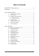
Table of Contents GA-8S661FXM-775 Motherboard Layout ..................................................................... 6 Block Diagram ................................................................................................................ 7 Chapter 1 Hardware Installation ..................................................................................... 9 1-1 1-2 Considerations Prior to Installation .................................................................... 9 Feature Summary .....
Chapter 3 Drivers Installation ...................................................................................... 49 3-1 Install Chipset Drivers .................................................................................... 49 3-2 3-3 Software Applications ..................................................................................... 50 Driver CD Information .................................................................................... 50 3-4 3-5 Hardware Information ............
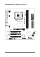
GA-8S661FXM-775 Motherboard Layout KB_MS ATX_12V ATX FDD LPT COMB COMA CPU_FAN SiS 661FX LAN USB USB VGA GA-8S661FXM-775 LGA775 F_AUDIO AUDIO IT8705AF IDE2 IDE1 DDR2 DDR1 AGP ICS1883 CLR_CMOS PCI1 SiS 964 SYS _FAN SATA1 PCI2 BIOS BAT CODEC PCI3 SUR_CEN CD_IN SPDIF_IO CI F_USB1 F_USB2 PWR_LED F_PANEL -6- SATA0
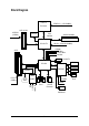
Block Diagram LGA775 Processor CPUCLK+/- (133/200MHz) AGP 4X/8X AGPCLK (66MHz) Host Interface VGA Port 266/333/400MHz DDR RAM SiS 661FX HCLK+/- (100/133/200MHz) 133MHz 33 MHz 14.
-8-
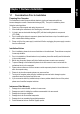
1-1 English Chapter 1 Hardware Installation Considerations Prior to Installation Preparing Your Computer The motherboard contains numerous delicate electronic circuits and components which can become damaged as a result of electrostatic discharge (ESD). Thus, prior to installation, please follow the instructions below: 1. Please turn off the computer and unplug its power cord. 2. When handling the motherboard, avoid touching any metal leads or connectors. 3.
English 1-2 Feature Summary CPU Chipset Memory Slots IDE Connections Onboard SATA FDD Connections Peripherals Onboard VGA Onboard LAN Onboard Audio I/O Control Hardware Monitor Supports the latest Intel® Pentium® 4 LGA775 CPU Supports 800/533MHz FSB L2 cache varies with processors Northbridge:SiS ® 661FX Southbridge: SiS® 964 2 184-pin DDR DIMM slots Supports DDR400/333/266 DIMM Supports up to 2GB (Max.) 1 AGP slot 4X/8X (1.
BIOS Additional Features Form Factor Onboard SiS964 chipset - supports data striping (RAID 0) or mirroring (RAID 1) function - supports JBOD function - supports data transfer rate of up to 150 MB/s - supports hot plugging function - supports a maximum of 2 SATA connections Use of licensed AWARD BIOS Supports Q-Flash Supports @BIOS Supports EasyTune Micro-ATX form factor; 24.4cm x 23.
English 1-3 Installation of the CPU and Heatsink Before installing the CPU, please comply with the following conditions: 1. Please make sure that the motherboard supports the CPU. 2. Please take note of the one indented corner of the CPU. If you install the CPU in the wrong direction, the CPU will not insert properly. If this occurs, please change the insert direction of the CPU. 3. Please add an even layer of heat sink paste between the CPU and heatsink. 4.
Male Push Pin The top of Female Push Pin Female Push Pin Fig.1 Please apply an even layer of heatsink paste on the surface of the installed CPU. Fig. 2 (Turning the push pin along the direction of arrow is to remove the heatsink, on the contrary, is to install.) Please note the direction of arrow sign on the male push pin doesn't face inwards before installation. (This instruction is only for Intel boxed fan) Fig.
English 1-4 Installation of Memory Before installing the memory modules, please comply with the following conditions: 1. Please make sure that the memory used is supported by the motherboard. It is recommended that memory of similar capacity, specifications and brand be used. 2 . Before installing or removing memory modules, please make sure that the computer power is switched off to prevent hardware damage. 3 . Memory modules have a foolproof insertion design.
Installation of Expansion Cards You can install your expansion card by following the steps outlined below: 1. Read the related expansion card's instruction document before installing the expansion card into the computer. 2. Remove your computer's chassis cover, screws and slot bracket from the computer. 3. Press the expansion card firmly into expansion slot in motherboard. 4. Be sure the metal contacts on the card are indeed seated in the slot. 5.
English 1-6 I/O Back Panel Introduction PS/2 Keyboard and PS/2 Mouse Connector To install a PS/2 port keyboard and mouse, plug the mouse to the upper port (green) and the keyboard to the lower port (purple). Parallel Port The parallel port allows connection of a printer, scanner and other peripheral devices. Serial Port Devices like mouses, modems, and etc. can be connected to Serial port. VGA Port Monitor can be connected to VGA port.
Connectors Introduction 1 3 English 1-7 2 16 6 5 8 18 15 4 7 10 11 1) 2) 3) 4) 5) 6) 7) 8) 9) 9 12 13 ATX_12V ATX CPU_FAN SYS_FAN IDE1/IDE2 FDD SATA0/SATA1 F_AUDIO SUR_CEN 10) 11) 12) 13) 14) 15) 16) 17) 18) - 17 - 14 17 F_PANEL CD_IN SPDIF_IO F_USB1/F_USB2 CI CLR_CMOS COMB PWR_LED BAT Hardware Installation
English 1/2) ATX_12V/ATX (Power Connector) With the use of the power connector, the power supply can supply enough stable power to all the components on the motherboard. Before connecting the power connector, please make sure that all components and devices are properly installed. Align the power connector with its proper location on the motherboard and connect tightly. The ATX_12V power connector mainly supplies power to the CPU. If the ATX_12V power connector is not connected, the system will not start.
CPU_FAN / SYS_FAN (Cooler Fan Power Connector) The cooler fan power connector supplies a +12V power voltage via a 3-pin/4-pin (only for CPU_FAN) power connector and possesses a fool-proof connection design. Most coolers are designed with color-coded power connector wires. A red power connector wire indicates a positive connection and requires a +12V power voltage. The black connector wire is the ground wire (GND). Please remember to connect the power to the cooler to prevent system overheating and failure.
English 5) IDE1/IDE2 (IDE Connector) An IDE device connects to the computer via an IDE connector. One IDE connector can connect to one IDE cable, and the single IDE cable can then connect to two IDE devices (hard drive or optical drive). If you wish to connect two IDE devices, please set the jumper on one IDE device as Master and the other as Slave (for information on settings, please refer to the instructions located on the IDE device).
Serial ATA can provide up to 150MB/s transfer rate. Please refer to the BIOS setting for the Serial ATA and install the proper driver in order to work properly. Pin No. 1 7 S_ATA (Control by SiS964) Definition 1 GND 2 3 TXP TXN 4 GND 5 RXN 6 7 RXP GND 8) F_AUDIO (Front Audio Panel Connector) Please make sure the pin assigment on the cable is the same as the pin assigment on the MB header. To find out if the chassis you are buying support front audio panel connector, please contact your dealer.
Please contact your nearest dealer for optional SUR_CEN cable. Pin No. 2 1 6 5 Definition 1 SUR OUTL 2 3 SUR OUTR GND 4 No Pin 5 CENTER_OUT 6 BASS_OUT 10) F_PANEL (Front Panel Connector) Please connect the power LED, PC speaker, reset switch and power switch etc. of your chassis front panel to the F_PANEL connector according to the pin assignments below.
English 11) CD_IN (CD IN Connector) Connect CD-ROM or DVD-ROM audio out to the connector. 1 Pin No. 1 Definition CD-L 2 GND 3 GND 4 CD-R 12) SPDIF_IO (SPDIF In/ Out) The SPDIF output is capable of providing digital audio to external speakers or compressed AC3 data to an external Dolby Digital Decoder. Use this feature only when your stereo system has digital input function. Use SPDIF IN feature only when your device has digital output function.
English 13) F1_USB / F2_USB (Front USB Connectors) Be careful with the polarity of the front USB connector. Check the pin assignment carefully while you connect the front USB cable, incorrect connection between the cable and connector will make the device unable to work or even damage it. For optional front USB cable, please contact your local dealer. 2 10 Pin No.
You may clear the CMOS data to its default values by this jumper. To clear CMOS, temporarily short pins 1-2. To prevent improper use of this header, we do not include a jumper on it. Open: Normal 1 Short: Clear CMOS 1 16) COMB (COMB Connector) Be careful with the polarity of the COMB connector. Check the pin assignments while you connect the COMB cable. Please contact your nearest dealer for optional COMB cable. Pin No.
English 17) PWR_LED PWR_LED is connected with the system power indicator to indicate whether the system is on/off. It will blink when the system enters suspend mode. Pin No. 1 Definition 1 MPD+ 2 3 MPDMPD- 18) BAT (Battery) Danger of explosion if battery is incorrectly replaced. Replace only with the same or equivalent type recommended by the manufacturer. Dispose of used batteries according to the manufacturer's instructions. If you want to erase CMOS... 1.
English - 27 - Hardware Installation
English GA-8S661FXM-775 Motherboard - 28 -
BIOS (Basic Input and Output System) includes a CMOS SETUP utility which allows user to configure required settings or to activate certain system features. The CMOS SETUP saves the configuration in the CMOS SRAM of the motherboard. When the power is turned off, the battery on the motherboard supplies the necessary power to the CMOS SRAM. When the power is turned on, pushing the button during the BIOS POST (Power-On Self Test) will take you to the CMOS SETUP screen.
English The Main Menu (For example: BIOS Ver. : E3) Once you enter Award BIOS CMOS Setup Utility, the Main Menu (as figure below) will appear on the screen. Use arrow keys to select among the items and press to accept or enter the sub-menu.
Change, set, or disable password. It allows you to limit access to the system and Setup, or just to Setup. Set User Password Change, set, or disable password. It allows you to limit access to the system. Save & Exit Setup Save CMOS value settings to CMOS and exit setup. Exit Without Saving Abandon all CMOS value changes and exit setup.
English 2-1 Standard CMOS Features CMOS Setup Utility-Copyright (C) 1984-2004 Award Software Standard CMOS Features ` ` ` ` Date (mm:dd:yy) Time (hh:mm:ss) Thu, July 29 2004 22:31:24 Item Help Menu Level IDE Channel 0 Master IDE Channel 0 Slave IDE Channel 1 Master IDE Channel 1 Slave [None] [None] [None] [None] Change the day, month, year Drive A Drive B Floppy 3 Mode Support [1.44M, 3.5"] [None] [Disabled] Sun. to Sat.
The category identifies the types of floppy disk drive A or drive B that has been installed in the computer. None No floppy drive installed 360K, 5.25" 5.25 inch PC-type standard drive; 360K byte capacity. 1.2M, 5.25" 5.25 inch AT-type high-density drive; 1.2M byte capacity (3.5 inch when 3 Mode is Enabled). 720K, 3.5" 3.5 inch double-sided drive; 720K byte capacity 1.44M, 3.5" 3.5 inch double-sided drive; 1.44M byte capacity. (Default value) 2.88M, 3.5" 3.5 inch double-sided drive; 2.88M byte capacity.
English 2-2 Advanced BIOS Features CMOS Setup Utility-Copyright (C) 1984-2004 Award Software Advanced BIOS Features ` Hard Disk Boot Priority First Boot Device Second Boot Device Third Boot Device Boot Up Floppy Seek Password Check CPU Hyper-Threading note 1 Limit CPUID Max.
During POST, BIOS will determine if the installed floppy disk drive is 40 or 80 tracks. 360K type is 40 tracks 720K, 1.2M and 1.44M are all 80 tracks. Disabled BIOS will not search for the type of floppy disk drive by track number. Note that there will not be any warning message if the drive installed is 360K. (Default value) Enabled BIOS searches for floppy disk drive to determine if it is 40 or 80 tracks. Note that BIOS can not tell from 720K, 1.2M or 1.44M drive type as they are all 80 tracks.
English 2-3 Integrated Peripherals CMOS Setup Utility-Copyright (C) 1984-2004 Award Software Integrated Peripherals IDE1 Conductor Cable IDE2 Conductor Cable On-Chip Primary PCI IDE On-Chip Secondary PCI IDE AC97 Audio Onboard LAN device USB Controller USB Legacy Support SiS Serial ATA Controller SiS Serial ATA Mode Onboard Serial Port 1 Onboard Serial Port 2 Onboard Parallel Port Parallel Port Mode ECP Mode Use DMA KLJI: Move Enter: Select F5: Previous Values [Auto] [Auto] [Enabled] [Enabled] [Enabled]
Enabled Disabled English Onboard LAN device Enable Onboard LAN device function. (Default value) Disable this function. USB Controller Enabled Disabled Enable USB Controller. (Default value) Disable USB Controller. USB Legacy Support Enabled Disabled Enable USB Legacy Support. Disable USB Legacy Support. (Default value) SiS Serial ATA Controller Enabled Disabled Enable SiS Serial ATA Controller.(Default value) Disable SiS Serial ATA Controller.
English 2-4 Power Management Setup CMOS Setup Utility-Copyright (C) 1984-2004 Award Software Power Management Setup ACPI Suspend Type Soft-Off by PWR_BTTN System After AC Back IRQ [3-7, 9-15], NMI ModemRingOn PME Event Wake Up Power On by Keyboard Power On by Mouse Resume by Alarm x Month Alarm x Day(of Month) x Time(hh:mm:ss) Power LED in S1 state KLJI: Move Enter: Select F5: Previous Values [S1(POS)] [Off] [Off] [Enabled] [Enabled] [Enabled] [Disabled] [Disabled] [Disabled] NA Everyday 0:0:0 [Blinkin
This feature requires an ATX power supply that provides at least 1A on the 5VSB lead. Disabled Disable this function. Enabled Enable PME Event Wake up. (Default value) Power On By Keyboard Password Disabled Any Key Enter one to five characters to set the Keyboard Power On password. Disabled this function. (Default value) Press any key to turn on the computer. Power On By Mouse Disabled Enabled Disable this function. (Default value) Move or click the left button of the PS/2 mouse to turn on the computer.
English 2-5 PnP/PCI Configurations CMOS Setup Utility-Copyright (C) 1984-2004 Award Software PnP/PCI Configurations PCI 1 IRQ Assignment PCI 2 IRQ Assignment PCI 3 IRQ Assignment [Auto] [Auto] [Auto] Item Help Menu Level ` Device(s) using this INT: RAID Cntrlr -Bus 0 Dev5 Func 0 KLJI: Move Enter: Select F5: Previous Values +/-/PU/PD: Value F6: Fail-Safe Defaults F10: Save ESC: Exit F1: General Help F7: Optimized Defaults PCI 1 IRQ Assignment Auto 3,4,5,7,9,10,11,12,14,15 Auto assign IRQ to PCI 1.
PC Health Status CMOS Setup Utility-Copyright (C) 1984-2004 Award Software PC Health Status Reset Case Open Status Case Opened Vcore DDR 2.5V +3.
English CPU Smart FAN Mode This option is available only when CPU Smart FAN Control is enabled. Auto Voltage PWM BIOS autodetects the type of CPU fan you installed and sets the optimal CPU Smart FAN control mode for it. (Default Value) Set to Voltage when you use a CPU fan with a 3-pin fan power cable. Set to PWM when you use a CPU fan with a 4-pin fan power cable. In fact, the Voltage option can be used for CPU fans with 3-pin or 4-pin power cables.
4T/5T/6T/7T/8T/9T Set DRAM RAS Active Time to 4T/5T/6T/7T/8T/9T. (Default value:9T) DRAM RAS Precharge Time 3T/2T/4T/5T Set DRAM RAS Precharge time to 2T/3T/4T/5T . (Default value:3T) DRAM RAS to CAS Delay 3T/2T/4T/5T Set DRAM RAS to CAS Delay to 3T/2T/4T/5T. (Default value:3T) CPU Clock Ratio (MHz) This setup option will be automatically assigned by CPU detection. The option will display "Locked" and read only if the CPU ratio is not changeable.
English 2-8 Top Performance CMOS Setup Utility-Copyright (C) 1984-2004 Award Software ` ` Standard CMOS Features Advanced BIOS Features ` ` Load Optimized Defaults Set Supervisor Password ` ` Integrated Peripherals Top Performance Power Management Setup Disabled.........................[] PnP/PCI Configurations Enabled..........................[ ] PC Health Status ` MB Intelligent Tweaker (M.I.T.
CMOS Setup Utility-Copyright (C) 1984-2004 Award Software ` Standard CMOS Features Top Performance ` ` Advanced BIOS Features Integrated Peripherals Load Fail-Safe Defaults Load Optimized Defaults ` ` Power Management Setup PnP/PCI Configurations ` ` PC Health Status MB Intelligent Tweaker (M.I.T.
English 2-12 Save & Exit Setup CMOS Setup Utility-Copyright (C) 1984-2004 Award Software ` Standard CMOS Features Top Performance ` ` Advanced BIOS Features Integrated Peripherals Load Fail-Safe Defaults Load Optimized Defaults ` ` Power Management Setup PnP/PCI Configurations ` ` PC Health Status MB Intelligent Tweaker (M.I.T.
English - 47 - BIOS Setup
English GA-8S661FXM-775 Motherboard - 48 -
Pictures below are shown in Windows XP. (1) Please make sure to install the latest service pack for Windows after OS installation and before installing motherboard drivers. (2) Insert the driver CD that came with your motherboard into your CD-ROM drive, the driver CD will auto start and installation screen will appear. If not, please double click the CD-ROM device icon in My computer or execute the Setup.exe in the root directory of the driver CD.
English 3-2 Software Applications This page displays all the tools that Gigabyte developed and some free software, you can choose anyone you want and press "install" to install them. 3-3 Driver CD Information This page lists the contents of software and drivers in this CD-title.
Hardware Information English 3-4 This page lists all device you have for this motherboard. 3-5 Contact Us You can also see the last page of this manual for contacts information details.
English GA-8S661FXM-775 Motherboard - 52 -
4-1 Appendix Unique Software Utility (Not all models support these unique software utilities, please check your motherboard features.) 4-1-1 Xpress Recovery2 Introduction Xpress Recovery2 is designed to provide quick backup and restoration of hard disk data. Supporting Microsoft operating systems including Windows XP/2000/NT/98/Me and DOS, and file systems including FAT16, FAT32, and NTFS, Xpress Recovery2 is able to back up data on hard disks on PATA and SATA IDE controllers.
English The Main Screen of Xpress Recovery2 1. RESTORE: Restore the backed-up data to your hard disk. (This button will not appear if there is no backup file.) 2. BACKUP: Back up data from hard disk. 3. REMOVE: Remove previously-created backup files to release disk space. (This button will not appear if there is no backup file.) 4. REBOOT: Exit the main screen and restart the system. Limitations: 1. 2. 3. Not compatible to Xpress Recovery.
Method 1 : Q-FlashTM Utility Q-Flash TM is a BIOS flash utility embedded in Flash ROM. With this utility, users only have to stay in the BIOS menu when they want to update BIOS. Q-Flash TM allows users to flash BIOS without any utility in DOS or Windows. Using Q-Flash TM indicating no more fooling around with any complicated instructions and operating system since it is in the BIOS menu.
English Entering the Q-FlashTM utility: Step1: To use Q-Flash utility, you must press Del in the boot screen to enter BIOS menu. CMOS Setup Utility-Copyright (C) 1984-2004 Award Software Standard CMOS Features Advanced BIOS Features Integrated Peripherals Power Management Setup PnP/PCI Configurations PC Health Status MB Intelligent Tweaker(M.I.T.
This section tells you how to update BIOS using the Q-Flash utility. As described in the "Before you begin" section above, you must prepare a floppy disk having the BIOS file for your motherboard and insert it to your computer. If you have already put the floppy disk into your system and have entered the Q-Flash utility, please follow the steps below to flash BIOS. Steps: 1.
English 3. Press Y button on your keyboard after you are sure to update BIOS. Then it will begin to update BIOS. The progress of updating BIOS will be displayed. Please do not take out the floppy disk when it begins flashing BIOS. 4. Press any keys to return to the Q-Flash menu when the BIOS updating procedure is completed. Dual BIOS Utility Boot From......................................... Main Bios Main ROM Type/Size.............................SST 49LF004A Backup ROM Type/Size.........................
Press Del to enter BIOS menu after system reboots. When you are in BIOS menu, move to Load Fail-Safe Defaults item and press Enter to load BIOS Fail-Safe Defaults. Normally the system redetects all devices after BIOS has been upgraded. Therefore, we highly recommend reloading the BIOS defaults after BIOS has been upgraded.
English Exploring the Q-FlashTM utility screen The Q-FlashBIOS utility screen consists of the following key components. Q-Flash Utility V1.30 Flash Type/Size.................................SST 49LF002A Task menu for Q-FlashTM utility Enter : Run Keep DMI Data Enable Update BIOS from Floppy Save BIOS to Floppy :Move ESC:Reset Q-FlashTM utility bar 256K F10:Power Off Action bar Task menu for Q-Flash utility: Contains the names of three tasks.
Press Y button on your keyboard after you are sure to update BIOS. Then it will begin to update BIOS. The progress of updating BIOS will be shown at the same time. Q-Flash Utility V1.30 Flash Type/Size.................................SST 49LF002A 256K Keep DMI Data BIOS Enable Updating Now Update BIOS from Floppy >>>>>>>>>>>>>>>>>>>......................... Save BIOS to Floppy EnterDon't : RunTurn Off Power :Move or Reset ESC:Reset F10:Power Off System 4.
English Method 2 : @BIOSTM Utility If you do not have a DOS startup disk, we recommend that you use the new @BIOS utility. @BIOS allows users to update their BIOS under Windows. Just select the desired @BIOS server to download the latest version of BIOS. Fig 1. Installing the @BIOS utility Fig 2. Installation complete and run @BIOS Click Start/ Programs/ GIGABYTE/@BIOS Click @BIOS item to Install Fig 3. The @BIOS utility Click " " Fig 4. Select the desired @BIOS server Click "Update New BIOS" 1.
IV. Check out supported motherboard and Flash ROM: In the very beginning, there is "About this program" icon shown in dialog box. It can help you check out which kind of motherboard and which brand of Flash ROM are supported. 2. Note: I. In method I, if it shows two or more motherboard's model names to be selected, please make sure your motherboard's model name again. Selecting wrong model name will cause the system unbooted. II.
English 4-1-3 Serial ATA BIOS Setting Utility Introduction RAID Levels RAID (Redundant Array of Independent Disks) is a method of combining two hard disk drives into one logical unit. The advantage of an Array is to provide better performance or data fault tolerance. Fault tolerance is achieved through data redundant operation, where if one drives fails, a mirrored copy of the data can be found on another drive. This can prevent data loss if the operating system fails or hangs.
Configuring the SiS RAID BIOS The SiS RAID BIOS Setting Utility lets you choose the RAID array type and which hard drives you want to make part of the array. Entering the RAID BIOS Setup After rebooting your computer, wait until you see the RAID software prompting you to press Ctrl-S (Figure 1). The RAID prompt appears as part of the system POST and boot process prior to loading the OS. You have a few seconds to press Ctrl-S before the window disappears. Silicon Integrated Systems Corp.
English Creating RAID Volume Step 1: In the RAID Setup window, press to create RAID volume (Figure 3). SiS RAID BIOS Setting Utility RAID Setup * Current Created Raid * Press [A] key to create RAID [Q] : Exit current menu Location Model Capacity Mode RAID Type Disk 1 Disk 2 ST3120026AS ST3120026AS 111GB 111GB UDMA 6 UDMA 6 Single Single Figure 3 Step 2: Then, use number keys 1~3 to select a RAID type: (1)JBOD, (2)RAID 0, or (3)RAID 1 and then press (Figure 4).
SiS RAID BIOS Setting Utility RAID Setup * Current Created Raid * RAID 0 <1> Auto Create <2> Manual Create : 1 [Q] : Exit current menu Location Model Capacity Mode RAID Type Disk 1 Disk 2 ST3120026AS ST3120026AS 111GB 111GB UDMA 6 UDMA 6 Single Single Figure 5 Step 4: If you wish to proceed to map and stripe all current data and future data to the RAID disks, press . Or press to perform striping on future data only. Then press (Figure 6).
English After the completion, you will see the RAID array under the * Current Created Raid * list in the RAID Setup window (Figure 7). SiS RAID BIOS Setting Utility RAID Setup * Current Created Raid * RAID 0 : Disk 1 Disk 2 Press [D] key to delete RAID [Q] : Exit current menu Location Model Capacity Mode RAID Type Disk 1 Disk 2 ST3120026AS ST3120026AS 111GB 111GB UDMA 6 UDMA 6 RAID0 RAID0 Figure 7 Step 5: To exit the current menu, press .
If you want to delete a RAID volume, simply press in the following window (Figure 9) and then use arrow keys to select the RAID Volume and press to confirm. Finally, when the "Are you sure to delete this RAID?" message appears, press to confirm your selections.
English Installing the RAID Drivers To install Windows 2000/XP onto a Serial ATA hard disk sucessfully, you need to install required driver for the SATA controller on your motherboard during OS installation. Without the driver, the hard disk may not be recognized during the Windows setup process. First of all, you have to copy the driver for the SATA controller on your motherboard from the motherboard driver CD to a floppy disk. See the instructions below about how to copy the driver.
The following setup is for Windows 98SE/2000/ME/XP. Please follow the steps below to enable the function! 2 Channel Audio Setup We recommend that you use speakers with amplifier to get the best sound effect if the stereo output is applied. STEP 1: Connect the stereo speakers or earphone to "Line Out." Line Out STEP 2: After installing the audio driver, you’ll find a Sound Effect icon on the lower right hand taskbar. Click the icon to select the function.
English 4 Channel Analog Audio Output Mode STEP 1: Connect the front channels to "Line Out," the rear channels to "Line In." Line Out Line In STEP 2: After installing the audio driver, you’ll find a Sound Effect icon on the lower right hand taskbar. Click the icon to select the function. STEP 3: On the AC97 Audio Configuration menu, click the Speaker Configuration tab and select the 4-channel mode for 4 speaker output check box. Clear the Only SURROUND-KIT check box and press OK.
English Basic 6 Channel Analog Audio Output Mode Use the back audio panel to connect the audio output without any additional module. STEP 1: Connect the front channels to "Line Out",the rear channels to "Line In", and the Center/Subwoofer channels to "MIC In". Line In MIC In Line Out STEP 2: After installing the audio driver, you’ll find a Sound Effect icon on the lower right hand taskbar. Click the icon to select the function.
English Advanced 6 Channel Analog Audio Output Mode (using Audio Combo Kit,Optional Device): (Audio Combo Kit provides SPDIF output port : optical & coaxis and SURROUND-KIT : Rear R/L & CEN /Subwoofer) SURROUND-KIT access analog output to rear channels and Center/Subwoofer channels. It is the best solution if you need 6 channel output, Line In and MIC at the same time. "SURROUND-KIT" is included in the GIGABYTE unique "Audio Combo Kit" as picture.
English STEP 3: Connect the front channels to back audio panel's "Line Out", the rear channels to SURROUND-KIT's REAR R/L, and the Center/Subwoofer channels to SURROUND-KIT's SUB CENTER. STEP 4: After installing the audio driver, you’ll find a Sound Effect icon on the lower right hand taskbar. Click the icon to select the function. STEP 5: On the AC97 Audio Configuration menu, click the Speaker Configuration tab and select the 6-channel mode for 5.1 speaker output check box.
English SPDIF Output Device (Optional Device) A "SPDIF output" device is an optional device. The SPDIF_IO cable with rear bracket could link to the "SPDIF_IO" connector (As picture.) For the further linkage to decoder, rear bracket provides coaxial cable and Fiber connecting port. STEP 1: Secure the metal bracket of the SPDIF Output device to the chassis back panel with a screw. STEP 2: Connect the SPDIF device cable to the SPDIF_IO connector on the motherboard.
English Jack-Sensing Introuction Jack-Sensing provides audio connectors error-detection function. Install Microsoft DirectX8.1 first to enable Jack-Sensing support for Windows 98SE/2000 /ME. Jack-Sensing includes 2 parts: AUTO and MANUAL. Following is an example for 2 channels (Windows XP): Introduction of audio connectors You may connect CDROM, Walkman or other audio input devices to Line In jack, speakers, earphone, other output devices to Line Out jack, and microphone to MIC In jack.
English If you set wrong with the connectors, the warning message will come out as right picture. Manual setting: If the device picture shows different from what you set, please press "Manual Selection" to set.
Troubleshooting Below is a collection of general asked questions. To check general asked questions based on a specific motherboard model, please log on to www.gigabyte.com.tw Question 1: I cannot see some options that were included in previous BIOS after updating BIOS. Why? Answer: Some advanced options are hidden in new BIOS version. Please press Ctrl and F1 keys after entering BIOS menu and you will be able to see these options.
English GA-8S661FXM-775 Motherboard - 80 -
English - 81 - Appendix
English GA-8S661FXM-775 Motherboard - 82 -
English - 83 - Appendix
English GA-8S661FXM-775 Motherboard - 84 -
English - 85 - Appendix
English GA-8S661FXM-775 Motherboard - 86 -
English Contact Us Taiwan (Headquarters) GIGA-BYTE TECHNOLOGY CO., LTD. Japan NIPPON GIGA-BYTE CORPORATION Address: No.6, Bau Chiang Road, Hsin-Tien, Taipei 231, Taiwan WEB address : http://www.gigabyte.co.jp Singapore TEL: +886-2-8912-4888 FAX: +886-2-8912-4003 GIGA-BYTE SINGAPORE PTE. LTD. Tech. Support : Tech. Support : http://tw.giga-byte.com/TechSupport/ServiceCenter.htm http://tw.giga-byte.com/TechSupport/ServiceCenter.htm Non-Tech. Support(Sales/Marketing) : Non-Tech.
English China Russia NINGBO G.B.T. TECH. TRADING CO., LTD. Tech. Support : Moscow Representative Office Of GIGA-BYTE Technology Co., Ltd. http://tw.giga-byte.com/TechSupport/ServiceCenter.htm Non-Tech. Support(Sales/Marketing) : Tech. Support : http://tw.giga-byte.com/TechSupport/ServiceCenter.htm http://ggts.gigabyte.com.tw/nontech.asp WEB address : http://www.gigabyte.com.cn Non-Tech. Support(Sales/Marketing) : http://ggts.gigabyte.com.tw/nontech.