GA-965GM-DS2 / GA-965GM-S2 Intel® CoreTM 2 Extreme quad-core / CoreTM 2 Quad / Intel® CoreTM 2 Extreme dual-core / CoreTM 2 Duo / Intel® Pentium® Processor Extreme Edition / Intel® Pentium® D / Pentium® 4 LGA775 Processor Motherboard User's Manual Rev.
Motherboard GA-965GM-DS2 / GA-965GM-S2 Oct. 1, 2006 Motherboard GA-965GM-DS2 / GA-965GM-S2 Oct.
Copyright © 2007 GIGA-BYTE TECHNOLOGY CO., LTD. All rights reserved. The trademarks mentioned in the manual are legally registered to their respective companies. Notice The written content provided with this product is the property of Gigabyte. No part of this manual may be reproduced, copied, translated, or transmitted in any form or by any means without Gigabyte's prior written permission. Specifications and features are subject to change without prior notice.
Table of Contents Item Checklist ................................................................................................................. 6 Optional Accessories ...................................................................................................... 6 GA-965GM-DS2 / GA-965GM-S2 Motherboard Layout ................................................. 7 Block Diagram ................................................................................................................
Chapter 3 Install Drivers ............................................................................................. 47 3-1 Install Chipset Drivers .................................................................................... 47 3-2 3-3 Software Applications ..................................................................................... 48 Driver CD Information .................................................................................... 48 3-4 3-5 Hardware Information ..........
Item Checklist IDE Cable x 1, FDD Cable x 1 SATA 3Gb/s Cable x 2 I/O Shield * The items listed above are for reference only, and are subject to change without notice. Optional Accessories 2 Ports USB 2.0 Cable (Part Number: 12CR1-1UB030-51/R) 4 Ports USB 2.
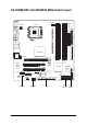
GA-965GM-DS2 / GA-965GM-S2 Motherboard Layout CPU_FAN Intel® G965 AUDIO F_AUDIO PCI1 Marvell 88E8056 BIOS PCI2 CODEC F_USB2 F_USB3 F1_1394 COMB SATAII2 BATTERY F2_1394 SPDIF_IO GIGABYTE SATA2 Intel® ICH8 CI CLR_CMOS SYS _FAN F_USB1 -7- IDE PWR_LED PCIE_1 CD_IN FDD DDRII3 PCIE_16 DDRII4 USB_LAN ATX DDRII2 USB_1394 DDRII1 VGA LPT GA-965GM-DS2 / GA-965GM-S2 COMA ATX_12V IT8718 LGA775 F_PANEL KB_MS SATAII3 SATAII0 SATAII1 GSATAII0 GSATAII1
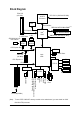
Block Diagram PCIe CLK (100 MHz) LGA775 Processor VGA CPU CLK+/-(266/200/133 MHz) Host Interface DDRII 800/667/533 MHz DIMM(Note) PCI Express x16 LAN 2 SATA 3Gb/s ATA-33/66/100/133 RJ45 IDE Channel GIGABYTE Marvell SATA2 88E8056 PCI Express Bus x1 Intel® G965 Dual Channel Memory GMCH CLK (266/200/133 MHz) x1 BIOS x1 4 SATA 3Gb/s PCIe CLK (100 MHz) Intel® ICH8 1 PCI Express x1 LPT PCI Bus IT8718 Floppy COM Ports TSB43AB23 2 PCI PCI CLK(33 MHz) (Note) PS/2 KB/Mouse SPDIF In SPDIF Out MI
1-1 English Chapter 1 Hardware Installation Considerations Prior to Installation Preparing Your Computer The motherboard contains numerous delicate electronic circuits and components which can become damaged as a result of electrostatic discharge (ESD). Thus, prior to installation, please follow the instructions below: 1. Please turn off the computer and unplug its power cord. 2. When handling the motherboard, avoid touching any metal leads or connectors. 3.
English 1-2 Feature Summary CPU LGA775 for Intel® Core 2 Extreme quad-core / Core 2 Extreme dual-core / Core 2 Quad / Core 2 Duo / Pentium ® processor Extreme Edition / Pentium ® D / Pentium ® 4 / Celeron ® D L2 cache varies with CPU Supports 1066/800/533 MHz FSB Northbridge: Intel ® G965 Express Chipset Southbridge: Intel ® ICH8 Onboard Marvell 88E8056 phy (10/100/1000 Mbit) Onboard Realtek ALC888 CODEC chip Supports High Definition Audio Supports 2 / 4 / 6 / 8 channel audio Supports SPDIF In/Out co
Rear Panel I/O I/O Control Hardware Monitor BIOS Additional Features Bundle Software Form Factor 3 USB 2.0/1.1 connectors for additional 6 USB 2.0/1.1 ports by cables 1 SPDIF In/Out connector 2 IEEE 1394a connectors for additional 2 ports by cable 1 COMB connector 1 Chassis Intrusion connector 1 PS/2 keyboard port 1 PS/2 mouse port 1 parallel port 1 VGA port 1 serial port (COMA) 4 USB 2.0/1.
English 1-3 Installation of the CPU and CPU Cooler Before installing the CPU, please comply with the following conditions: 1. Please make sure that the motherboard supports the CPU. 2. Please take note of the one indented corner of the CPU. If you install the CPU in the wrong direction, the CPU will not insert properly. If this occurs, please change the insert direction of the CPU. 3. Please add an even layer of heat sink paste between the CPU and heatsink. 4.
Male Push Pin The top of Female Push Pin Female Push Pin Fig.1 Please apply an even layer of CPU cooler paste on the surface of the installed CPU. Fig. 2 (Turning the push pin along the direction of arrow is to remove the CPU cooler, on the contrary, is to install.) Please note the direction of arrow sign on the male push pin doesn't face inwards before installation. (This instruction is only for Intel boxed fan) Fig.
English 1-4 Installation of Memory Before installing the memory modules, please comply with the following conditions: 1. Please make sure that the memory used is supported by the motherboard. It is recommended that memory of similar capacity, specifications and brand be used. 2. Before installing or removing memory modules, please make sure that the computer power is switched off to prevent hardware damage. 3. Memory modules have a foolproof insertion design.
The GA-965GM-DS2 / GA-965GM-S2 supports the Dual Channel Technology. After operating the Dual Channel Technology, the bandwidth of memory bus will double. The GA-965GM-DS2 / GA-965GM-S2 includes 4 DIMM sockets, and each Channel has two DIMM sockets as following: Channel 0 : DDRII1, DDRII2 Channel 1 : DDRII3, DDRII4 If you want to operate the Dual Channel Technology, please note the following explanations due to the limitation of Intel chipset specifications. 1.
English 1-5 Installation of Expansion Cards You can install your expansion card by following the steps outlined below: 1. Read the related expansion card's instruction document before install the expansion card into the computer. 2. Remove your computer's chassis cover, screws and slot bracket from the computer. 3. Press the expansion card firmly into expansion slot in motherboard. 4. Be sure the metal contacts on the card are indeed seated in the slot. 5.
I/O Back Panel Introduction English 1-6 PS/2 Keyboard and PS/2 Mouse Connector To install a PS/2 port keyboard and mouse, plug the mouse to the upper port (green) and the keyboard to the lower port (purple). Parallel Port (LPT) The parallel port allows connection of a printer, scanner and other peripheral devices. Serial Port (COMA) Devices like mouses, modems, and etc. can be connected to Serial port. VGA Port Monitor can be connected to VGA port. IEEE 1394 port Connectec to IEEE 1394 devices.
English Line Out (Front Speaker Out) The default Line Out (Front Speaker Out) jack. Stereo speakers, earphone or front surround speakers can be connected to Line Out (Front Speaker Out) jack. MIC In The default MIC In jack. Microphone must be connected to MIC In jack. In addition to the default speakers settings, the ~ audio jacks can be reconfigured to perform different functions via the audio software. Only microphones still MUST be connected to the default Mic In jack ( ).
ATX_12V/ATX (Power Connector) With the use of the power connector, the power supply can supply enough stable power to all the components on the motherboard. Before connecting the power connector, please make sure that all components and devices are properly installed. Align the power connector with its proper location on the motherboard and connect tightly. The ATX_12V power connector mainly supplies power to the CPU. If the ATX_12V power connector is not connected, the system will not start.
English 3/4) CPU_FAN / SYS_FAN (Cooler Fan Power Connector) The cooler fan power connector supplies a +12V power voltage via a 4-pin power connector and possesses a foolproof connection design. Most coolers are designed with color-coded power connector wires. A red power connector wire indicates a positive connection and requires a +12V power voltage. The black connector wire is the ground wire (GND).
The FDD connector is used to connect the FDD cable while the other end of the cable connects to the FDD drive. The types of FDD drives supported are: 360 KB, 720 KB, 1.2 MB, 1.44 MB and 2.88 MB. Before attaching the FDD cable, please take note of the foolproof groove in the FDD connector. 34 33 2 1 7) SATAII0 / 1 / 2 / 3 (SATA 3Gb/s Connector, Controlled by Intel ICH8) SATA 3Gb/s can provide up to 300 MB/s transfer rate.
English 8) GSATAII0/1 (SATA 3Gb/s Connector, Controlled by GIGABYTE SATA2) SATA 3Gb/s can provide up to 300 MB/s transfer rate. Please refer to the BIOS setting for the SATA 3Gb/s and install the proper driver in order to work properly. GSATAII0 7 1 Pin No. 1 1 7 2 3 TXP TXN 4 5 GND RXN 6 7 RXP GND GSATAII1 Definition GND 9) PWR_LED The PWR_LED connector is connected with the system power indicator to indicate whether the system is on/off.
Please connect the power LED, PC speaker, reset switch and power switch etc of your chassis front panel to the F_PANEL connector according to the pin assignment below.
English 11) F_AUDIO (Front Audio Connector) This connector supports either HD (High Definition) or AC97 front panel audio module. If you wish to use the front audio function, connect the front panel audio module to this connector. Check the pin assignments carefully while you connect the front panel audio module. Incorrect connection between the module and connector will make the audio device unable to work or even damage it. For optional front panel audio module, please contact your chassis manufacturer.
English 12) CD_IN (CD In Connector) Connect CD-ROM or DVD-ROM audio out to the connector. Pin No. 1 1 Definition CD-L 2 3 GND GND 4 CD-R 13) SPDIF_IO (SPDIF In/Out Connector) The SPDIF output is capable of providing digital audio to external speakers or compressed AC3 data to an external Dolby Digital Decoder. Use this feature only when your stereo system has digital input function. Use SPDIF IN feature only when your device has digital output function.
English 14) F_USB1 / F_USB2 / F_USB3 (Front USB Connectors) Be careful with the polarity of the front USB connector. Check the pin assignment carefully while you connect the front USB cable, incorrect connection between the cable and connector will make the device unable to work or even damage it. For optional front USB cable, please contact your local dealer. 9 10 1 2 Pin No.
Be careful with the polarity of the COMB connector. Check the pin assignments while you connect the COMB cable. Please contact your nearest dealer for optional COMB cable. 2 10 1 9 Pin No. Definition 1 2 NDCDBNSINB 3 4 NSOUTB NDTRB- 5 6 GND NDSRB- 7 8 NRTSBNCTSB- 9 10 NRIBNo Pin 17) CI (Chassis Intrusion, Case Open) This 2-pin connector allows your system to detect if the chassis cover is removed. You can check the "Case Opened" status in BIOS Setup. Pin No.
English 18) CLR_CMOS (Clear CMOS) You may clear the CMOS data to its default values by this header. To clear CMOS, temporarily short the two pins. Default doesn't include the jumper to avoid improper use of this header. Open: Normal Short: Clear CMOS 19) BATTERY Danger of explosion if battery is incorrectly replaced. Replace only with the same or equivalent type recommended by the manufacturer. Dispose of used batteries according to the manufacturer's instructions. If you want to erase CMOS... 1.
BIOS (Basic Input and Output System) includes a CMOS SETUP utility which allows user to configure required settings or to activate certain system features. The CMOS SETUP saves the configuration in the CMOS SRAM of the motherboard. When the power is turned off, the battery on the motherboard supplies the necessary power to the CMOS SRAM. When the power is turned on, pushing the button during the BIOS POST (Power-On Self Test) will take you to the CMOS SETUP screen.
English : Boot Menu Select boot sequence for onboard (or add-on cards) device. Award Modular BIOS v6.00PG, An Energy Star Ally Copyright (C) 1984-2006, Award Software, Inc. Intel G965 BIOS for 965GM-DS2 F1 . . . . :BIOS Setup/Q-Flash, : Xpress Recovery2, : Boot Menu 10/12/2006-G965-ICH8-6A79LG0PC-00 : Boot Menu Use < > or < > to select a device, then press enter to accept. Press to exit this menu.
English Standard CMOS Features This setup page includes all the items in standard compatible BIOS. Advanced BIOS Features This setup page includes all the items of Award special enhanced features. Integrated Peripherals This setup page includes all onboard peripherals. Power Management Setup This setup page includes all the items of Green function features. PnP/PCI Configurations This setup page includes all the configurations of PCI & PnP ISA resources.
English 2-1 Standard CMOS Features CMOS Setup Utility-Copyright (C) 1984-2006 Award Software Standard CMOS Features ` ` ` ` ` ` ` ` Date (mm:dd:yy) Time (hh:mm:ss) Fri, Mar 18 2006 18:25:04 IDE Channel 0 Master IDE Channel 1 Master IDE Channel 2 Master IDE Channel 3 Master IDE Channel 4 Master IDE Channel 4 Slave IDE Channel 5 Master IDE Channel 5 Slave [None] [None] [None] [None] [None] [None] [None] [None] Drive A Floppy 3 Mode Support [1.44M, 3.
Access Mode Capacity Cylinder Head Precomp Landing Zone Sector Select this if no IDE/SATA devices are used and the system will skip the automatic detection step and allow for faster system start up. Use this to set the access mode for the hard drive. The two options are: Large/Auto(default:Auto) Capacity of currently installed hard disk.
English 2-2 Advanced BIOS Features CMOS Setup Utility-Copyright (C) 1984-2006 Award Software Advanced BIOS Features ` Hard Disk Boot Priority First Boot Device Second Boot Device Third Boot Device Password Check HDD S.M.A.R.T. Capability CPU Hyper-Threading (Note) Limit CPUID Max.
This feature allows your hard disk to report read/write errors and to issue warnings when thirdparty hardware monitor utility is installed. Enabled Enable HDD S.M.A.R.T. capability. Disabled Disable HDD S.M.A.R.T. capability. (Default value) CPU Hyper-Threading (Note) Enabled Disabled Enable CPU Hyper Threading Feature. Please note that this feature is only working for operating system with multi processors mode supported. (Default value) Disable CPU Hyper Threading. Limit CPUID Max.
English 2-3 Integrated Peripherals CMOS Setup Utility-Copyright (C) 1984-2006 Award Software Integrated Peripherals SATA Port0-3 Native Mode USB Controller USB 2.
Enabled Disabled English Onboard H/W 1394 Enable onboard IEEE1394 function. (Default value) Disable onboard IEEE1394 function. Onboard H/W LAN Enabled Disabled Enable Onboard H/W LAN function. (Default value) Disable this function. SMART LAN (LAN Cable Diagnostic Function) CMOS Setup Utility-Copyright (C) 1984-2006 Award Software SMART LAN Start detecting at Port.....
English OnBoard LAN Boot ROM This function decide whether to invoke the boot ROM of the onboard LAN chip. Enabled Enable this function. Disabled Disable this function. (Default value) Onboard SATA/IDE Device This function allows users to enable or disable the SATA/IDE ports controlled by the GIGABYTE SATA2 controller. Enabled Enable this function.(Default value) Disabled Disable this function.
Power Management Setup English 2-4 CMOS Setup Utility-Copyright (C) 1984-2006 Award Software Power Management Setup ACPI Suspend Type Soft-Off by PWR-BTTN PME Event Wake Up Power On by Ring Resume by Alarm x Date (of Month) Alarm x Time (hh:mm:ss) Alarm Power On By Mouse Power On By Keyboard x KB Power ON Password AC Back Function KLJI: Move Enter: Select F5: Previous Values [S1(POS)] [Instant-Off] [Enabled] [Enabled] [Disabled] Everyday 0:0:0 [Disabled] [Disabled] Enter [Soft-Off] +/-/PU/PD: Value F6
English Power On By Keyboard Disabled Password Keyboard 98 Disable this function. (Default value) Enter from 1 to 5 characters to set the Keyboard Power On Password. If your keyboard have "POWER Key" button, you can press the key to power on the system. KB Power ON Password When "Power On by Keyboard" set at Password, you can set the password here. Enter Input password (from 1 to 5 characters) and press Enter to set the Keyboard Power On password.
PC Health Status CMOS Setup Utility-Copyright (C) 1984-2006 Award Software PC Health Status Reset Case Open Status Case Opened Vcore DDR18V +3.
English Smart FAN Control Method (Note) Auto Intel(R) QST Legacy Disable BIOS sets the optimal CPU fan speed automatically. (Default value) Control the fan speed with Intel® QST (Intel ® Quiet System Technology). CPU fan runs at different speed depending on CPU temperature. CPU fan runs at full speed. Smart FAN Control Mode Auto BIOS autodetects the type of CPU fan you installed and sets the optimal fan speed control mode for it.
Frequency/Voltage Control CMOS Setup Utility-Copyright (C) 1984-2006 Award Software Frequency/Voltage Control CPU Clock Ratio (Note) System Memory Multiplier Memory Frequency (Mhz) KLJI: Move Enter: Select F5: Previous Values [16X] [Auto] 533 +/-/PU/PD: Value F6: Fail-Safe Defaults Item Help Menu Level` F10: Save ESC: Exit F1: General Help F7: Optimized Defaults Incorrectly using these features may result in system instability or corruption.
English 2-8 Load Fail-Safe Defaults CMOS Setup Utility-Copyright (C) 1984-2006 Award Software ` ` ` ` ` ` ` Standard CMOS Features Advanced BIOS Features Integrated Peripherals Power Management Setup PnP/PCI Configurations PC Health Status Frequency/Voltage Control Load Fail-Safe Defaults Load Optimized Defaults Set Supervisor Password Set User Password Load Fail-Safe DefaultsSave (Y/N)? &N Exit Setup Exit Without Saving KLJI: Select Item F10: Save & Exit Setup ESC: Quit F8: Q-Flash Load Fail-Safe Def
English 2-10 Set Supervisor/User Password CMOS Setup Utility-Copyright (C) 1984-2006 Award Software ` ` ` ` ` ` ` Standard CMOS Features Advanced BIOS Features Integrated Peripherals Power Management Setup PnP/PCI Configurations Enter Password: PC Health Status Frequency/Voltage Control Load Fail-Safe Defaults Load Optimized Defaults Set Supervisor Password Set User Password Save & Exit Setup Exit Without Saving KLJI: Select Item F10: Save & Exit Setup ESC: Quit F8: Q-Flash Change/Set/Disable Password
English 2-11 Save & Exit Setup CMOS Setup Utility-Copyright (C) 1984-2006 Award Software ` ` ` ` ` ` ` Standard CMOS Features Advanced BIOS Features Integrated Peripherals Power Management Setup PnP/PCI Configurations PC Health Status Frequency/Voltage Control Load Fail-Safe Defaults Load Optimized Defaults Set Supervisor Password Save to CMOS and EXIT (Y/N)? Y Password Set User Save & Exit Setup Exit Without Saving KLJI: Select Item F10: Save & Exit Setup ESC: Quit F8: Q-Flash Save Data to CMOS Type
Pictures below are shown in Windows XP. Insert the driver CD-title that came with your motherboard into your CD-ROM drive, the driver CD-title will auto start and show the installation guide. If not, please double click the CD-ROM device icon in "My computer", and execute the Run.exe. 3-1 Install Chipset Drivers After insert the driver CD, "Xpress Install" will scan automatically the system and then list all the drivers that recommended to install.
English 3-2 Software Applications This page displays all the tools that Gigabyte developed and some free software, you can choose anyone you want and press "install" to install them. 3-3 Driver CD Information This page lists the contents of software and drivers in this CD-title.
Hardware Information English 3-4 This page lists all device you have for this motherboard. 3-5 Contact Us Please see the last page for details.
English GA-965GM-(D)S2 Motherboard - 50 -
4-1 English Chapter 4 Appendix Unique Software Utilities (Not all model support these Unique Software Utilities, please check your MB features.) 4-1-1 EasyTune 5 Introduction EasyTune 5 presents the most convenient Windows based system performance enhancement and manageability utility. Featuring several powerful yet easy to use tools such as 1) Overclocking for enhancing system performance, 2) C.I.A. and M.I.B.
English 4-1-2 Xpress Recovery2 Introduction Xpress Recovery2 is designed to provide quick backup and restoration of hard disk data. Supporting Microsoft operating systems including Windows XP/2000/NT/98/Me and DOS, and file systems including FAT16, FAT32, and NTFS, Xpress Recovery2 is able to back up data on hard disks on PATA and SATA IDE controllers. After Xpress Recovery2 is executed from CD-ROM for the first time, it will stay permanent in your hard disk.
1. RESTORE: Restore the backed-up data to your hard disk. (This button will not appear if there is no backup file.) 2. BACKUP: Back up data from hard disk. 3. REMOVE: Remove previously-created backup files to release disk space. (This button will not appear if there is no backup file.) 4. REBOOT: Exit the main screen and restart the system. Limitations: 1. 2. 3. Not compatible to Xpress Recovery. For the use of Xpress Recovery2, a primary partition must be reserved.
English 4-1-3 Flash BIOS Method Introduction Method 1 : Q-FlashTM Utility Q-FlashTM is a BIOS flash utility embedded in Flash ROM. With this utility, users only have to stay in the BIOS menu when they want to update BIOS. Q-Flash TM allows users to flash BIOS without any utility in TM DOS or Windows. Using Q-Flash indicating no more fooling around with any complicated instructions and operating system since it is in the BIOS menu.
English Entering the Q-FlashTM utility: Step1: To use Q-Flash utility, you must press Del in the boot screen to enter BIOS menu. CMOS Setup Utility-Copyright (C) 1984-2004 Award Software Standard CMOS Features Advanced BIOS Features Integrated Peripherals Power Management Setup PnP/PCI Configurations PC Health Status MB Intelligent Tweaker(M.I.T.
English Using the Q-FlashTM utility: This section tells you how to update BIOS using the Q-Flash utility. As described in the "Before you begin" section above, you must prepare a floppy disk having the BIOS file for your motherboard and insert it to your computer. If you have already put the floppy disk into your system and have entered the Q-Flash utility, please follow the steps below to flash BIOS. Steps: 1.
English 3. Press Y button on your keyboard after you are sure to update BIOS. Then it will begin to update BIOS. The progress of updating BIOS will be displayed. Please do not take out the floppy disk when it begins flashing BIOS. 4. Press any keys to return to the Q-Flash menu when the BIOS updating procedure is completed. Dual BIOS Utility Boot From......................................... Main Bios Main ROM Type/Size.............................SST 49LF003A Backup ROM Type/Size.........................
English 6. Press Del to enter BIOS menu after system reboots. When you are in BIOS menu, move to Load Optimized Defaults item and press Enter to load BIOS Optimized Defaults. Normally the system redetects all devices after BIOS has been upgraded. Therefore, we highly recommend reloading the BIOS defaults after BIOS has been upgraded.
The Q-FlashBIOS utility screen consists of the following key components. Q-FlashTM utility bar Q-Flash Utility V1.30 Flash Type/Size.................................SST 49LF003A Task menu for Q-FlashTM utility Enter : Run Keep DMI Data Enable Update BIOS from Floppy Save BIOS to Floppy :Move ESC:Reset 256K F10:Power Off Action bar Task menu for Q-Flash utility: Contains the names of three tasks. Blocking a task and pressing Enter key on your keyboard to enable execution of the task.
English 3. Press Y button on your keyboard after you are sure to update BIOS. Then it will begin to update BIOS. The progress of updating BIOS will be shown at the same time. Q-Flash Utility V1.30 Flash Type/Size.................................SST 49LF003A 256K Keep DMI Data BIOS Enable Updating Now Update BIOS from Floppy >>>>>>>>>>>>>>>>>>>......................... Save BIOS to Floppy EnterDon't : Run :Moveor ResetESC:Reset F10:Power Off Turn Off Power System 4.
If you do not have a DOS startup disk, we recommend that you use the new @BIOS utility. @BIOS allows users to update their BIOS under Windows. Just select the desired @BIOS server to download the latest version of BIOS. Fig 1. Installing the @BIOS utility Fig 2. Installation Complete and Run @BIOS Click Start/ Programs/ GIGABYTE/@BIOS Select @BIOS item than click Install Fig 3. The @BIOS Utility Click "3" Fig 4. Select the desired @BIOS server Click "Update New BIOS" 1. Methods and steps: I.
English III. Save BIOS In the very beginning, there is "Save Current BIOS" icon shown in dialog box. It means to save the current BIOS version. IV. Check out supported motherboard and Flash ROM: In the very beginning, there is "About this program" icon shown in dialog box. It can help you check out which kind of motherboard and which brand of Flash ROM are supported. 2. Note: I.
English 4-1-4 Configuring SATA Hard Drive(s) (Controller: GIGABYTE SATA2) To configure SATA hard drive(s), follow the steps below: (1) Install SATA hard drive(s) in your system. (2) Configure SATA controller mode and boot sequence in BIOS Setup. (3) Configure RAID array in RAID BIOS.(Note 1) (4) Make a floppy disk containing the SATA controller driver. (Note 2) (5) Install the SATA controller driver during OS installation.
English (2) Configuring SATA controller mode and boot sequence in BIOS Setup You have to make sure whether the SATA controller is configured correctly in system BIOS Setup and set BIOS boot sequence for the SATA hard drive(s)/RAID array. Step 1: Turn on your computer and press Del to enter BIOS Setup during POST (Power-On Self Test). In BIOS Setup, go to Integrated Periperals, set Onboard SATA/IDE Ctrl Mode to RAID/IDE before configuring RAID.
CMOS Setup Utility-Copyright (C) 1984-2006 Award Software Advanced BIOS Features Hard Disk Boot Priority First Boot Device Second Boot Device Third Boot Device Password Check CPU Hyper-Threading Limit CPUID Max.
English (3) Configuring RAID array in RAID BIOS Enter the RAID BIOS setup utility to configure a RAID array. Skip this step if you do not want to create RAID. Step 1: After the POST memory test begins and before the operating system boot begins, look for a message which says "Press to enter RAID Setup Utility" (Figure 3). Press CTRL+ G to enter the GIGABYTE SATA2 RAID BIOS setup utility. GIGA-BYTE Technology Corp. PCIE-to-SATAII/IDE RAID Controller BIOS v1.06.
In the main screen, press ENTER on the Create RAID Disk Drive item. Then the RAID creation screen appears (Figure 5). GIGA-BYTE Technology Corp. PCIE-to-SATAII/IDE RAID Controller BIOS V1.06.
English 3. Assign Array Disks: After RAID mode is selected, RAID BIOS automatically assigns the two hard disks installed as the RAID disks. 4. Set Block Size (only for RAID 0): Under the Block item, use the UP or DOWN ARROW key to select the block size (Figure 7), ranging from 4K to 128K. Press ENTER when finished. GIGA-BYTE Technology Corp. PCIE-to-SATAII/IDE RAID Controller BIOS V1.06.
GIGA-BYTE Technology Corp. PCIE-to-SATAII/IDE RAID Controller BIOS V1.06.
English To check more detailed information about the array, use the TAB key while in the Main Menu block to move the selection bar to the RAID Disk Drive List block. Select the array and press ENTER. A small window displaying the array information will appear in the center of the screen (Figure 11). GIGA-BYTE Technology Corp. PCIE-to-SATAII/IDE RAID Controller BIOS V1.06.
To delete the array, select Delete RAID Disk Drive in the main menu and press ENTER. The selection bar will move to the RAID Disk Drive List block. Press the SPACEBAR on the array to be deleted; a small triangle will appear to mark the selected array (Figure 13). Press Del. GIGA-BYTE Technology Corp. PCIE-to-SATAII/IDE RAID Controller BIOS V1.06.
English (4) Making a SATA Driver Disk (Required for AHCI and RAID Mode) To install operating system onto a serial ATA hard disk successfully, you need to install the SATA controller driver during OS installation. Without the driver, the hard disk may not be recognized during the Windows setup process. First of all, copy the driver for the SATA controller from the motherboard driver CD-ROM to a floppy disk. See the instructions below about how to copy the driver in MS-DOS mode(Note1).
Now that you have prepared the SATA driver disk and configured BIOS settings, you are ready to install Windows 2000/XP onto your SATA hard drive with the SATA driver. The following is an example of Windows XP installation. Step 1: Restart your system to boot from the Windows 2000/XP Setup disk and press F6 as soon as you see the "Press F6 if you need to install a 3rd party SCSI or RAID driver" message (Figure 18).
English Step 3: If Setup correctly recognizes the driver in the floppy disk, a controller menu similar to Figure 20 below will appear. Use the ARROW keys to select GIGABYTE GBB363 RAID Controller (Windows 2K/XP/2003)(Note) and press ENTER.Then it will begin to load the SATA driver from the floppy disk. Windows Setup You have chosen to configure a SCSI Adapter for use with Windows, using a device support disk provided by an adapter manufacturer.
WindowsXP Professional Setup Welcome to Setup. This port of the Setup program prepares Microsoft(R) Windows (R) XP to run on your computer. To set up Windows XP now, press ENTER. To repair a Windows XP installation using Recovery Console, press R. To quit Setup without installing Windows XP, press F3. Enter= Continue R=Repair F3=Exit Figure 22 (Note: Each time you add a new hard drive to a RAID array, the RAID driver will have to be installed under Windows once for that hard drive.
English 4-1-5 2- / 4- / 6- / 8- Channel Audio Function Introduction The default speaker settings for the 6 audio jacks are as shown in the picture to the right. The jack retasking capability supported by HD Audio allows users to change the function for each audio jack by the audio software provided. For example, if a rear speaker is plugged into the center/subwoofer speaker out jack, you can change the center/ subwoofer speaker out jack to fucntion as a rear speaker out jack via the audio software.
English STEP 2: In the Audio Control Panel, click the Audio I/O tab. In the upper left list, click 2CH Speaker. STEP 3: After a speaker or headphone is plugged into the rear Line Out jack, a small window will pop up and ask you what type of equipment is connected. Choose Headphone or Line Out depending on the device connected and click OK. The 2-channel audio setup is completed.
English STEP 3: After plugging in 4-channel speakers to the rear speaker jacks, a small window will pop up and ask you what type of equipment is connected. Choose a device depending on the type of speaker connected (4-channel audio consists of Front Speaker Out (Line Out) and Rear Speaker Out) and then click OK. The 4-channel audio setup is completed.
English 8 Channel Audio Setup STEP 1 : After installation of the audio driver, you should find an Audio Manager icon in your system tray (you can also find the icon in Control Panel). Doubleclick the icon to open the Audio Control Panel. STEP 2: In the Audio Control Panel, click the Audio I/O tab. In the upper left list, click 8CH Speaker. STEP 3: After plugging in 8-channel speakers to the rear speaker jacks, a small window will pop up and ask you what type of equipment is connected.
English Sound Effect Configuration: At the Sound Effect menu, users can adjust sound option settings as desired. AC'97 Audio Configuration: To enable the front panel audio connector to support AC97 Audio mode, go to the Audio Control Panel and click the Audio I/O tab. In the ANALOG area, click the Tool icon and then select the Disable front panel jack detection check box. This action completes the AC'97 Audio configuration.
Troubleshooting Below is a collection of general asked questions. To check general asked questions based on a specific motherboard model, please log on to http://www.gigabyte.com.tw Question 1: I cannot see some options that were included in previous BIOS after updating BIOS. Why? Answer: Some advanced options are hidden in new BIOS version. Please press Ctrl and F1 keys after entering BIOS menu and you will be able to see these options.
English GA-965GM-(D)S2 Motherboard - 82 -
English - 83 - Appendix
English GA-965GM-(D)S2 Motherboard - 84 -
English - 85 - Appendix
English Contact Us y Taiwan (Headquarters) GIGA-BYTE TECHNOLOGY CO., LTD. y China NINGBO G.B.T. TECH. TRADING CO., LTD. Address: No.6, Bau Chiang Road, Hsin-Tien, Taipei 231, Taiwan WEB address : http://www.gigabyte.cn Shanghai TEL: +886-2-8912-4888 FAX: +886-2-8912-4003 TEL: +86-21-63410999 FAX: +86-21-63410100 Tech. and Non-Tech. Support (Sales/Marketing) : http://ggts.gigabyte.com.tw Beijing TEL: +86-10-62102838 WEB address (English): http://www.gigabyte.com.tw WEB address (Chinese): http://www.
y Russia Moscow Representative Office Of GIGA-BYTE Technology Co., Ltd. WEB address : http://www.gigabyte.ru y Latvia G.B.T. TECH. CO., LTD. WEB address : http://www.giga-byte.co.uk y The Netherlands GIGA-BYTE Latvia WEB address : http://www.gigabyte.com.lv y Poland GIGA-BYTE TECHNOLOGY B.V. WEB address : http://www.giga-byte.nl y France Office of GIGA-BYTE TECHNOLOGY Co., Ltd. in POLAND GIGABYTE TECHNOLOGY FRANCE WEB address : http://www.gigabyte.pl y Ukraine WEB address : http://www.gigabyte.
- 88 -