GA-B85M-D3H User's Manual Rev.
Motherboard GA-B85M-D3H Motherboard GA-B85M-D3H Apr. 19, 2013 Apr. 19, 2013 Copyright © 2013 GIGA-BYTE TECHNOLOGY CO., LTD. All rights reserved. The trademarks mentioned in this manual are legally registered to their respective owners. Disclaimer Information in this manual is protected by copyright laws and is the property of GIGABYTE. Changes to the specifications and features in this manual may be made by GIGABYTE without prior notice.
Table of Contents GA-B85M-D3H Motherboard Layout................................................................................4 GA-B85M-D3H Motherboard Block Diagram....................................................................5 Chapter 1 Hardware Installation......................................................................................6 1-1 1-2 1-3 1-4 1-5 1-6 1-7 Installation Precautions.....................................................................................
ATX_12V_2X4 SYS_FAN1 DDR3_1 DDR3_3 KB_MS_USB DDR3_2 DDR3_4 GA-B85M-D3H Motherboard Layout CPU_FAN VGA_DVI ATX LGA1150 HDMI F_USB30 R_USB30 GA-B85M-D3H BAT 1 3 SATA3 0 2 Realtek® GbE LAN SYS_FAN2 AUDIO 1 SATA2 0 USB_LAN iTE® Super I/O PCIEX16 PCI1 Intel® B85 B_BIOS PCI2 M_BIOS CODEC SYS_FAN3 PCIEX4 CLR_CMOS TPM F_AUDIO COM SPDIF_O LPT F_USB2 F_USB1 F_PANEL Box Contents 55 55 55 55 GA-B85M-D3H motherboard Motherboard driver disk User's Manual Quick Installation Guide 55 Two
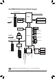
GA-B85M-D3H Motherboard Block Diagram PCI Express Bus CPU CLK+/- (100 MHz) x16 1 PCI Express x16 DVI-D LGA1150 CPU DDR3 1600/1333 MHz Dual Channel Memory DMI 2.0 FDI HDMI PCIe CLK (100 MHz) Dual BIOS D-Sub 4 SATA 6Gb/s LAN PCIe CLK (100 MHz) PCI Express Bus x4 2 SATA 3Gb/s RJ45 Realtek® GbE LAN Intel® B85 4 USB 3.0/2.0 x1 8 USB 2.0/1.
Chapter 1 Hardware Installation 1-1 Installation Precautions The motherboard contains numerous delicate electronic circuits and components which can become damaged as a result of electrostatic discharge (ESD). Prior to installation, carefully read the user's manual and follow these procedures: •• Prior to installation, make sure the chassis is suitable for the motherboard. •• Prior to installation, do not remove or break motherboard S/N (Serial Number) sticker or warranty sticker provided by your dealer.
1-2 Product Specifications CPU Support for Intel® Core™ i7 processors/Intel® Core™ i5 processors/ Intel® Core™ i3 processors/Intel® Pentium® processors/Intel® Celeron® processors in the LGA1150 package (Go to GIGABYTE's website for the latest CPU support list.) L3 cache varies with CPU Chipset Intel® B85 Express Chipset Memory 4 x 1.
Internal Connectors Back Panel Connectors 1 x 24-pin ATX main power connector 1 x 8-pin ATX 12V power connector 4 x SATA 6Gb/s connectors 2 x SATA 3Gb/s connectors 1 x CPU fan header 3 x system fan headers 1 x front panel header 1 x front panel audio header 1 x S/PDIF Out header 1 x USB 3.0/2.0 header 2 x USB 2.0/1.
Bundled Software Operating System Norton Internet Security (OEM version) Intel® Rapid Start Technology Intel® Smart Connect Technology Intel® Small Business Advantage Support for Windows 8/7 Form Factor Micro ATX Form Factor; 24.4cm x 22.5cm * GIGABYTE reserves the right to make any changes to the product specifications and product-related information without prior notice.
Dual Channel Memory Configuration This motherboard provides four DDR3 memory sockets and supports Dual Channel Technology. After the memory is installed, the BIOS will automatically detect the specifications and capacity of the memory. Enabling Dual Channel memory mode will double the original memory bandwidth.
Triple-Display Configurations for the Onboard Graphics: Triple-display configurations are supported after you install motherboard drivers in OS. Only dual-display configurations are supported during the BIOS Setup or POST process. USB 3.0/2.0 Port The USB 3.0 port supports the USB 3.0 specification and is compatible to the USB 2.0/1.1 specification. Use this port for USB devices Use this port for USB devices such as a USB keyboard/mouse, USB printer, USB flash drive and etc.
1-7 Internal Connectors 1 4 3 2 11 7 5 4 6 10 16 9 1) ATX_12V_2X4 2) 3) 13 14 15 12 4 8 9) F_AUDIO ATX 10) SPDIF_O CPU_FAN 11) F_USB30 4) SYS_FAN1/SYS_FAN2/SYS_FAN3 12) F_USB1/2 5) BAT 13) COM 6) SATA3 0/1/2/3 14) LPT 7) SATA2 0/1 15) TPM 8) F_PANEL 16) CLR_CMOS Read the following guidelines before connecting external devices: •• First make sure your devices are compliant with the connectors you wish to connect.
1/2) ATX_12V_2X4/ATX (2x4 12V Power Connector and 2x12 Main Power Connector) With the use of the power connector, the power supply can supply enough stable power to all the components on the motherboard. Before connecting the power connector, first make sure the power supply is turned off and all devices are properly installed. The power connector possesses a foolproof design. Connect the power supply cable to the power connector in the correct orientation.
5) BAT (Battery) The battery provides power to keep the values (such as BIOS configurations, date, and time information) in the CMOS when the computer is turned off. Replace the battery when the battery voltage drops to a low level, or the CMOS values may not be accurate or may be lost. You may clear the CMOS values by removing the battery: 1. Turn off your computer and unplug the power cord. 2. Gently remove the battery from the battery holder and wait for one minute.
8) F_PANEL (Front Panel Header) •• •• •• SPEAK- PWR_LED+ PWR_LEDPWR_LED- HD+ HDRESRES+ CICI+ SPEAK+ Connect the power switch, reset switch, speaker, chassis intrusion switch/sensor and system status indicator on the chassis to this header according to the pin assignments below. Note the positive and negative pins before connecting the cables. Power LED Power Switch Speaker •• PLED/PWR_LED (Power LED): Connects to the power status indicator System Status LED on the chassis front panel.
10) SPDIF_O (S/PDIF Out Header) This header supports digital S/PDIF Out and connects a S/PDIF digital audio cable (provided by expansion cards) for digital audio output from your motherboard to certain expansion cards like graphics cards and sound cards.
BIOS_PH (GA-IVB) 13) COM (Serial Port Header) The COM header can provide one serial port via an optional COM port cable. For purchasing the optional COM port cable, please contact the local dealer. 1 2 DEBUG PORT Definition NDCDNSIN NSOUT NDTRGND F_USB3 (Front Panel) XDP_CPU XDP_PCH (GA-IVB) 9 10 Pin No. 1 2 3 4 5 CLR_CMOS CI DIS_ME GP15_CPT (GA-IVB) SMB_CPT (GA-IVB) ACPI_CPT (GA-IVB) Pin No.
15) CLR_CMOS (Clear CMOS Jumper) Use this jumper to clear the BIOS configurations and reset the CMOS values to factory defaults. To clear the CMOS values, use a metal object like a screwdriver to touch the two pins for a few seconds. Open: Normal Short: Clear CMOS Values •• Always turn off your computer and unplug the power cord from the power outlet before clearing the CMOS values.
2-1 Startup Screen The following startup Logo screen will appear when the computer boots. (Sample BIOS Version: D9) Function Keys On the main menu of the BIOS Setup program, press arrow keys to move among the items and press to accept or enter a sub-menu. Or you can use your mouse to select the item you want. •• When the system is not stable as usual, select the Load Optimized Defaults item to set your system to its defaults.
`` M.I.T. Current Status This screen provides information on CPU/memory frequencies/parameters. `` Advanced Frequency Settings && Processor Graphics Clock Allows you to set the onboard graphics clock. The adjustable range is from 400 MHz to 4000 MHz. (Default: Auto) && CPU Clock Ratio Allows you to alter the clock ratio for the installed CPU. The adjustable range is dependent on the CPU being installed. && CPU Frequency Displays the current operating CPU frequency.
&& Hyper-Threading Technology (Note 1) Allows you to determine whether to enable multi-threading technology when using an Intel® CPU that supports this function. This feature only works for operating systems that support multi-processor mode. Auto lets the BIOS automatically configure this setting. (Default: Auto) && CPU Enhanced Halt (C1E) (Note 1) Enables or disables Intel® CPU Enhanced Halt (C1E) function, a CPU power-saving function in system halt state.
`` Advanced Memory Settings && Extreme Memory Profile (X.M.P.) (Note), System Memory Multiplier, Memory Frequency(MHz) The settings above are synchronous to those under the same items on the Advanced Frequency Settings menu. && Performance Enhance Allows the system to operate at three different performance levels. Normal Lets the system operate at its basic performance level. Turbo Lets the system operate at its good performance level.
`` PC Health Status && Reset Case Open Status Disabled Keeps or clears the record of previous chassis intrusion status. (Default) Enabled Clears the record of previous chassis intrusion status and the Case Open field will show "No" at next boot. && Case Open Displays the detection status of the chassis intrusion detection device attached to the motherboard CI header. If the system chassis cover is removed, this field will show "Yes", otherwise it will show "No".
Manual Allows you to control the fan speed under the Slope PWM item. Disabled Allows the fan to run at full speeds. && Slope PWM Allows you to control the fan speed. This item is configurable only when 2nd/3rd System Fan Speed Control is set to Manual. Options are: 0.75 PWM value /oC ~ 2.50 PWM value /oC. `` Miscellaneous Settings && PEG Gen3 Slot Configuration Allows you to set the operation mode of the PCI Express slots to Gen 1, Gen 2, or Gen 3.
&& Access Level Displays the current access level depending on the type of password protection used. (If no password is set, the default will display as Administrator.) The Administrator level allows you to make changes to all BIOS settings; the User level only allows you to make changes to certain BIOS settings but not all. 2-4 BIOS Features && Boot Option Priorities Specifies the overall boot order from the available devices.
&& Full Screen LOGO Show Allows you to determine whether to display the GIGABYTE Logo at system startup. Disabled skips the GIGABYTE Logo when the system starts up. (Default: Enabled) && Fast Boot Enables or disables Fast Boot to shorten the OS boot process. Ultra Fast provides the fastest bootup speed. (Default: Disabled) && VGA Support Allows you to select which type of operating system to boot. Auto Enables legacy option ROM only. EFI Driver Enables EFI option ROM.
&& OS Type Allows you to select the operating system to be installed. Set this item to Windows 8 for Windows 8 operating system. (Default: Other OS) && CSM Support Enables or disables UEFI CSM (Compatibility Support Module) to support a legacy PC boot process. Always Enables UEFI CSM. (Default) Never Disables UEFI CSM and supports UEFI BIOS boot process only. This item is configurable only when OS Type is set to Windows 8 or Windows 8 WHQL.
&& Administrator Password Allows you to configure an administrator password. Press on this item, type the password, and then press . You will be requested to confirm the password. Type the password again and press . You must enter the administrator password (or user password) at system startup and when entering BIOS Setup. Differing from the user password, the administrator password allows you to make changes to all BIOS settings.
Auto BIOS routes the sharable ports to EHCI controller. Then it uses ACPI protocols to provide an option to enable the xHCI controller and reroute the sharable ports. Note: This is the recommended mode when BIOS does NOT have xHCI pre-boot support. Enabled All shared ports are eventually routed to the xHCI controller during the BIOS boot process.
`` SATA Configuration && SATA Controller(s) Enables or disables the integrated SATA controllers. (Default: Enabled) && SATA Mode Selection Enables or disables RAID for the SATA controllers integrated in the Intel® B85 Chipset or configures the SATA controllers to AHCI mode. IDE Configures the SATA controller to IDE mode. AHCI Configures the SATA controller to AHCI mode.
2-6 Power Management && Resume by Alarm Determines whether to power on the system at a desired time. (Default: Disabled) If enabled, set the date and time as following: Wake up day: Turn on the system at a specific time on each day or on a specific day in a month. Wake up hour/minute/second: Set the time at which the system will be powered on automatically.
&& Power On By Keyboard Allows the system to be turned on by a PS/2 keyboard wake-up event. Note: To use this function, you need an ATX power supply providing at least 1A on the +5VSB lead. Disabled Disables this function. (Default) Password Set a password with 1~5 characters to turn on the system. Keyboard 98 Press POWER button on the Windows 98 keyboard to turn on the system. Any Key Press any key to turn on the system.
&& Load Optimized Defaults Press on this item and select Yes to load the optimal BIOS default settings. The BIOS defaults settings help the system to operate in optimum state. Always load the Optimized defaults after updating the BIOS or after clearing the CMOS values. && Boot Override Allows you to select a device to boot immediately. Press on the device you select and select Yes to confirm. Your system will restart automatically and boot from that device.
Regulatory Statements Regulatory Notices This document must not be copied without our written permission, and the contents there of must not be imparted to a third party nor be used for any unauthorized purpose. Contravention will be prosecuted. We believe that the information contained herein was accurate in all respects at the time of printing. GIGABYTE cannot, however, assume any responsibility for errors or omissions in this text.
- 35 -
Contact Us GIGA-BYTE TECHNOLOGY CO., LTD. Address: No.6, Bao Chiang Road, Hsin-Tien Dist., New Taipei City 231,Taiwan TEL: +886-2-8912-4000, FAX: +886-2-8912-4005 Tech. and Non-Tech. Support (Sales/Marketing) : http://ggts.gigabyte.com.tw WEB address (English): http://www.gigabyte.com WEB address (Chinese): http://www.gigabyte.tw You may go to the GIGABYTE website, select your language in the language list on the top right corner of the website.