
User`s manual
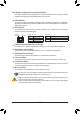

10) SPDIF_O(S/PDIFOutHeader)
This header supports digital S/PDIF Out and connects a S/PDIF digital audio cable (provided by expansion
cards) for digital audio output from your motherboard to certain expansion cards like graphics cards and
sound cards. For example, some graphics cards may require you to use a S/PDIF digital audio cable for
digital audio output from your motherboard to your graphics card if you wish to connect an HDMI display
to the graphics card and have digital audio output from the HDMI display at the same time. For information
about connecting the S/PDIF digital audio cable, carefully read the manual for your expansion card.
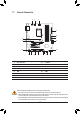
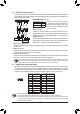
1
Pin No. Denition
1 SPDIFO
2 GND
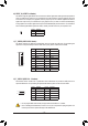
Pin No. Denition Pin No. Denition
1 VBUS 11 D2+
2 SSRX1- 12 D2-
3 SSRX1+ 13 GND
4 GND 14 SSTX2+
5 SSTX1- 15 SSTX2-
6 SSTX1+ 16 GND
7 GND 17 SSRX2+
8 D1- 18 SSRX2-
9 D1+ 19 VBUS
10 NC 20 No Pin
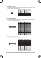
11) F_USB30 (USB 3.0/2.0 Header)
TheheaderconformstoUSB3.0/2.0specicationandcanprovidetwoUSBports.Forpurchasingthe
optional 3.5" front panel that provides two USB 3.0/2.0 ports, please contact the local dealer.
F_USB30
F_AUDIO(H)
DB_PORT
F_PANEL(NH) F_PANEL
(H61M-D2)
ACPI_CPT
(GA-IVB)
BIOS_PH
(GA-IVB)
SMB_CPT
(GA-IVB)
CLR_CMOS
CI
DIS_ME
GP15_CPT
(GA-IVB)
XDP_CPU
XDP_PCH
(GA-IVB)
TPM
w/housing
Voltage measurement module(X58A-OC)
PCIe power connector (SATA)(X58A-OC)
DIP
123
DIP
123
DIP
123
DIP
123
1
1
1
1
BIOS Switcher (X58A-OC)
PWM Switch (X58A-OC)
M_SATA
PWM Switch (SW1)(X79-UD7)
DIP
1 2 3 4 5
Voltage measurement points(G1.Sniper 3)
BIOS Switcher (SW4)
PCIe Control (Z87X-UP7)
DIP
1 2 3
4
DIP
1 2 3 4
DIP
1 2 3
4
DIP
1 2 3 4
ATX_12V_2X3
F_USB3 (Front Panel)
10
20 1
11
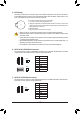
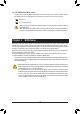
12) F_USB1/2 (USB 2.0/1.1 Headers)
TheheadersconformtoUSB2.0/1.1specication.EachUSBheadercanprovidetwoUSBportsviaan
optional USB bracket. For purchasing the optional USB bracket, please contact the local dealer.
Pin No. Denition Pin No. Denition
1 Power (5V) 6 USB DY+
2 Power (5V) 7 GND
3 USB DX- 8 GND
4 USB DY- 9 No Pin
5 USB DX+ 10 NC
• Do not plug the IEEE 1394 bracket (2x5-pin) cable into the USB 2.0/1.1 header.
• Prior to installing the USB bracket, be sure to turn off your computer and unplug the power cord
from the power outlet to prevent damage to the USB bracket.
10
9
2
1
- 16 -