GA-E2100N User's Manual Rev.
Motherboard GA-E2100N Motherboard GA-E2100N Jan. 13, 2014 Jan. 13, 2014 Copyright © 2014 GIGA-BYTE TECHNOLOGY CO., LTD. All rights reserved. The trademarks mentioned in this manual are legally registered to their respective owners. Disclaimer Information in this manual is protected by copyright laws and is the property of GIGABYTE. Changes to the specifications and features in this manual may be made by GIGABYTE without prior notice.
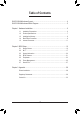
Table of Contents GA-E2100N Motherboard Layout.....................................................................................4 GA-E2100N Motherboard Block Diagram........................................................................5 Chapter 1 Hardware Installation......................................................................................6 1-1 1-2 1-3 1-4 1-5 Installation Precautions.....................................................................................
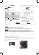
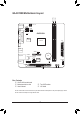
KB_MS_USB DDR3_1 DDR3_2 GA-E2100N Motherboard Layout ATX_12V F_USB1 COMB COMA F_USB2 GA-E2100N LPT CI VGA iTE® Super I/O ATX APU FT3 HDMI R_USB30 SATA3 0 1 USB_LAN Realtek® GbE LAN CPU_FAN PCIe to PCI Bridge F_AUDIO AUDIO SPDIF_O BAT F_PANEL CLR_CMOS SYS_FAN CODEC PCI M_BIOS B_BIOS Box Contents 55 GA-E2100N motherboard 55 Motherboard driver disk 55 User's Manual 55 Two SATA cables 55 I/O Shield The box contents above are for reference only and the actual items shall depend on the p
GA-E2100N Motherboard Block Diagram APU CLK+/- (100 MHz) DISP CLK+/- (100 MHz) DDR3 1333 MHz LAN Memory RJ45 Realtek® GbE LAN D-Sub AMD APU HDMI x1 PCI Express Bus Dual BIOS x1 PCIe to PCI Bridge 2 USB 3.0/2.0 8 USB 2.0/1.1 2 SATA 6Gb/s LPC Bus For detailed product information/limitation(s), refer to "1-2 Product Specifications.
Chapter 1 1-1 Hardware Installation Installation Precautions The motherboard contains numerous delicate electronic circuits and components which can become damaged as a result of electrostatic discharge (ESD). Prior to installation, carefully read the user's manual and follow these procedures: •• Prior to installation, make sure the chassis is suitable for the motherboard. •• Prior to installation, do not remove or break motherboard S/N (Serial Number) sticker or warranty sticker provided by your dealer.
1-2 Product Specifications APU Built in with an AMD® E1-2100 (1.0 GHz) APU with Radeon™ HD 8210 SoC Memory 1MB L2 cache 2 x DDR3 DIMM sockets supporting up to 32 GB of system memory * Do not disassemble the onboard SoC and the heatsink by yourself to avoid damage to these components. * Due to a Windows 32-bit operating system limitation, when more than 4 GB of physical memory is installed, the actual memory size displayed will be less than the size of the physical memory installed.
Back Panel Connectors I/O Controller iTE® I/O Controller Chip Hardware Monitor System voltage detection APU/System temperature detection APU/System fan speed detection APU/System fan speed control 2 x 32 Mbit flash Use of licensed AMI UEFI BIOS Support for DualBIOS™ PnP 1.0a, DMI 2.7, SM BIOS 2.7, ACPI 2.
1-3 Installing the Memory Read the following guidelines before you begin to install the memory: •• Make sure that the motherboard supports the memory. It is recommended that memory of the same capacity, brand, speed, and chips be used. (Go to GIGABYTE's website for the latest supported memory speeds and memory modules.) •• Always turn off the computer and unplug the power cord from the power outlet before installing the memory to prevent hardware damage. •• Memory modules have a foolproof design.
RJ-45 LAN Port The Gigabit Ethernet LAN port provides Internet connection at up to 1 Gbps data rate. The following describes the states of the LAN port LEDs. Connection/ Speed LED Activity LED LAN Port Connection/Speed LED: State Orange Green Off Activity LED: Description 1 Gbps data rate 100 Mbps data rate 10 Mbps data rate State Blinking Off Description Data transmission or receiving is occurring No data transmission or receiving is occurring Line In Jack (Blue) The default line in jack.
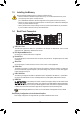
1-5 Internal Connectors 1 10 9 13 2 5 3 4 6 8 1) 2) 3) 4) 5) 6) 7) ATX_12V ATX CPU_FAN SYS_FAN SATA3 0/1 F_PANEL SPDIF_O 7 12 8) 9) 10) 11) 12) 13) 11 F_AUDIO F_USB1/F_USB2 COMB CLR_CMOS BAT CI Read the following guidelines before connecting external devices: •• First make sure your devices are compliant with the connectors you wish to connect. •• Before installing the devices, be sure to turn off the devices and your computer.
1/2) ATX_12V/ATX (2x2 12V Power Connector and 2x12 Main Power Connector) With the use of the power connector, the power supply can supply enough stable power to all the components on the motherboard. Before connecting the power connector, first make sure the power supply is turned off and all devices are properly installed. The power connector possesses a foolproof design. Connect the power supply cable to the power connector in the correct orientation.
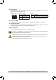
5) SATA3 0/1 (SATA 6Gb/s Connectors) The SATA connectors conform to SATA 6Gb/s standard and are compatible with SATA 3Gb/s and SATA 1.5Gb/s standard. Each SATA connector supports a single SATA device. Pin No. 1 2 3 4 5 6 7 7 1 SATA3 0 1 Definition GND TXP TXN GND RXN RXP GND 6) F_PANEL (Front Panel Header) Connect the power switch, reset switch, and system status indicator on the chassis to this header according to the pin assignments below.
8) F_AUDIO (Front Panel Audio Header) The front panel audio header supports Intel High Definition audio (HD) and AC'97 audio. You may connect your chassis front panel audio module to this header. Make sure the wire assignments of the module connector match the pin assignments of the motherboard header. Incorrect connection between the module connector and the motherboard header will make the device unable to work or even damage it. 9 10 1 2 For HD Front Panel Audio: Pin No.
11) CLR_CMOS (Clear CMOS Jumper) Use this jumper to clear the BIOS configuration and reset the CMOS values to factory defaults. To clear the CMOS values, use a metal object like a screwdriver to touch the two pins for a few seconds. Open: Normal Short: Clear CMOS Values •• Always turn off your computer before clearing the CMOS values.
Chapter 2 BIOS Setup BIOS (Basic Input and Output System) records hardware parameters of the system in the CMOS on the motherboard. Its major functions include conducting the Power-On Self-Test (POST) during system startup, saving system parameters and loading operating system, etc. BIOS includes a BIOS Setup program that allows the user to modify basic system configuration settings or to activate certain system features.
2-2 M.I.T. This section provides information on the BIOS version, CPU base clock, CPU frequency, memory frequency, total memory size, CPU temperature, Vcore, and memory voltage. Whether the system will work stably with the overclock/overvoltage settings you made is dependent on your overall system configurations. Incorrectly doing overclock/overvoltage may result in damage to CPU, chipset, or memory and reduce the useful life of these components.
&& SVM Mode Virtualization enhanced by Virtualization Technology will allow a platform to run multiple operating systems and applications in independent partitions. With virtualization, one computer system can function as multiple virtual systems. (Default: Enabled) && C6 Mode Allows you to determine whether to let the CPU enter C6 mode in system halt state. When enabled, the CPU core frequency will be reduced during system halt state to decrease power consumption.
`` PC Health Status && Reset Case Open Status Disabled Keeps or clears the record of previous chassis intrusion status. (Default) Enabled Clears the record of previous chassis intrusion status and the Case Open field will show "No" at next boot. && Case Open Displays the detection status of the chassis intrusion detection device attached to the motherboard CI header. If the system chassis cover is removed, this field will show "Yes", otherwise it will show "No".
2-3 System Information This section provides information on your motherboard model and BIOS version. You can also select the default language used by the BIOS and manually set the system time. && System Language Selects the default language used by the BIOS. && System Date Sets the system date. The date format is week (read-only), month, date, and year. Use to switch between the Month, Date, and Year fields and use the or key to set the desired value.
2-4 BIOS Features && Boot Option Priorities Specifies the overall boot order from the available devices. For example, you can set hard drive as the first priority (Boot Option #1) and DVD ROM drive as the second priority (Boot Option #2). The list only displays the device with the highest priority for a specific type. For example, only hard drive defined as the first priority on the Hard Drive BBS Priorities submenu will be presented here.
&& Fast Boot Enables or disables Fast Boot to shorten the OS boot process. Ultra Fast provides the fastest bootup speed. (Default: Disabled) && VGA Support Allows you to select which type of operating system to boot. Auto Enables legacy option ROM only. EFI Driver Enables EFI option ROM. (Default) This item is configurable only when Fast Boot is set to Enabled or Ultra Fast. && USB Support Disabled All USB devices are disabled before the OS boot process completes.
&& Other PCI Device ROM Priority Allows you to select whether to enable the UEFI or Legacy option ROM for the PCI device controller other than the LAN, storage device, and graphics controllers. Legacy OpROM Enables legacy option ROM only. UEFI OpROM Enables UEFI option ROM only. (Default) && Network stack Disables or enables booting from the network to install a GPT format OS, such as installing the OS from the Windows Deployment Services server.
&& HD Audio Azalia Device Enables or disables the onboard audio function. (Default: Enabled) If you wish to install a 3rd party add-in audio card instead of using the onboard audio, set this item to Disabled. && Onboard LAN Controller Enables or disables the onboard LAN function. (Default: Enabled) If you wish to install a 3rd party add-in network card instead of using the onboard LAN, set this item to Disabled. && OnChip USB Controller Enables or disables the integrated USB controller.
&& PORT0 Hot Plug~PORT1 Hot Plug Enables or disable the hot plug capability for each SATA port. (Default: Disabled) && SATA Power on PORT0~SATA Power on PORT1 Enables or disables each SATA port. (Default: Enabled) `` Super IO Configuration This section provides information on the super I/O chip and allows you to configure the serial port and parallel port. && Serial Port A/B Enables or disables the onboard serial port.
&& HPET Timer Enables or disables High Precision Event Timer (HPET) for Windows 8/7/Vista operating system. (Default: Enabled) && Soft-Off by PWR-BTTN Configures the way to turn off the computer in MS-DOS mode using the power button. Instant-Off Press the power button and then the system will be turned off instantly. (Default) Delay 4 Sec. Press and hold the power button for 4 seconds to turn off the system.
2-7 Save & Exit && Save & Exit Setup Press on this item and select Yes. This saves the changes to the CMOS and exits the BIOS Setup program. Select No or press to return to the BIOS Setup Main Menu. && Exit Without Saving Press on this item and select Yes. This exits the BIOS Setup without saving the changes made in BIOS Setup to the CMOS. Select No or press to return to the BIOS Setup Main Menu.
Chapter 3 Appendix Drivers Installation •• Before installing the drivers, first install the operating system. (The following instructions use Windows 8 as the example operating system.) •• After installing the operating system, insert the motherboard driver disk into your optical drive. Click on the message "Tap to choose what happens with this disc" on the top-right corner of the screen and select "Run Run.exe." (Or go to My Computer, double-click the optical drive and execute the Run.exe program.
Regulatory Statements Regulatory Notices This document must not be copied without our written permission, and the contents there of must not be imparted to a third party nor be used for any unauthorized purpose. Contravention will be prosecuted. We believe that the information contained herein was accurate in all respects at the time of printing. GIGABYTE cannot, however, assume any responsibility for errors or omissions in this text.
FCC Notice (U.S.A. Only) This equipment has been tested and found to comply with the limits for a Class B digital device, pursuant to Part 15 of the FCC Rules. These limits are designed to provide reasonable protection against harmful interference in a residential installation. This equipment generates, uses, and can radiate radio frequency energy and, if not installed and used in accordance with the instructions, may cause harmful interference to radio communications.
- 31 -
Contact Us GIGA-BYTE TECHNOLOGY CO., LTD. Address: No.6, Bao Chiang Road, Hsin-Tien Dist., New Taipei City 231,Taiwan TEL: +886-2-8912-4000, FAX: +886-2-8912-4005 Tech. and Non-Tech. Support (Sales/Marketing) : http://ggts.gigabyte.com.tw WEB address (English): http://www.gigabyte.com WEB address (Chinese): http://www.gigabyte.tw You may go to the GIGABYTE website, select your language in the language list on the top right corner of the website.